


An Improved Injection-pump Tester
Page 70
If you've noticed an error in this article please click here to report it so we can fix it.
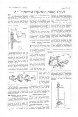
THE Hartridge injection-pomp tester is a well-known piece of apparatus arid patent No. 729,431 shows the latest improvements in the design of such devices. The patentee. is L. Hartridge, Tingewick Road, Buckingham. The device may be used with a known good injector to test .a doubtful pump or vice versa.
A standard injector (I) is fitted with a special upper cap unit (2). This contains a coil which is. magnetically affected when the needle valve rises, generating a small current at the moment that movement starts. The current is fed through an amplifier (3) and causes a neon lamp (4) to light at the precise moment.
On the spindle of the injection pump is a pointer which traverses a calibrated disc (5). When the lamp lights, it momentarily illuminates the pointer stroboscopically, and enables the exact angle at which injection commence's to be read off the dial.
All the plungers of a multi-cylindered pump can have Their outputs connected to the tester, in which case the-. disc would bc illuminated at a number of points, thus indicating the phtise angle between the charges.
PREVENTING AN OIL ENGINE FROM REVERSING
IF an oil engine accidentally backfires 1. there is nothing to prevent it from continuing to run backwards, drawing its air from the exhaust system and' exhausting out of the air intake. To render this impossible by preventing the injection pump from being reversed is the aim of a scheme shown in patent No. 730,644. The patentee is The
A36 Standard Motor Co., Ltd., Banner Lane, Coventry.
A special coupling is used in the drive to the pump; this is shown in an exploded view in the drawing. The pump spindle (I) carries one unit of the coupling: this is provided with three angular slots (2) in its flange. Mating with this is a male member having three corresponding angular projections (3). The male member is free to slide on splines (4) and is spring-loaded into engagement.
In the event of a reversal of drive, the clutch will disengage due to the angle of slope of the teeth, whilst correct rotation causes automatic re-engagement. The clutch cannot re-engage in a mistimed position , because the teeth are unevenly spaced and can mate only once per revolution.
A NOVEL REFUSE-COLLECTING SCHEME
THE normal way of collecting refuse
is for the dustman to walk to the house, collect the bin and empty it, and then walk back to replace it. To cut out this double journey is the aim of a scheme outlined in patent No. 730,882.
It is proposed to take an empty bin to the house, leave it and come away with the filled one. This means that some householders may complain that their clean bins had been replaced by inferior ones, Part of the scheme therefore is that each bin shall be cleaned and disinfected before reissue.
The drawing shows the vehicle used to perform this operation. In a tunnel under the main body is a power-driven bristle brush (1) over which the bin can be passed. The bristles are helically spaced so that they extract all the sweepings.
After the bin has been swept out, a charge of disinfectant is added from a box (2). The scheme may, of course, be used with the ordinary non-change bin system.
The patent is taken out in the names of the Lord Mayor, Aldermen and Citizens of the City of Nottingham.
DIPPING HEADLIGHTS
PATENT NO. 730,455 (Ford Motor Co., Ltd., 88 Regent Street, London, WI) describes a controller which automatically dips the headlights when meeting other lights. The operative unit is a photo-electric cell.
OVERHEAD-CAMSHAFT DRIVE THE method of coupling two parallel shafts by means of a pair of connecting-rods 90 degrees apart is well
known in the sewing-machine industry, but patent No. 730,369, shows the same scheme applied to an overhead-camshaft drive. The patentee is -Daimler-Benz' A.G., Sturtgart-Unterturkheim, Germany.
Whilst this type of drive is positive and compact, it is one which could' easily be upset by uneven heat-expansion, and the basis of the patent is a means for overcoming this difficulty.
The drawing shows a view of the front end of an engine. The two crankpins (I) are spaced 90 degrees apart and are coupled to an identical pair at the lower end by a pair of light con
Reefing rods. The 90-degree displacement ensures complete freedom from dead centres.
At the bottom, the drive is not taken . directly from the crankshaft but from the second pinion of an oil pump (2). The pump is permitted to rock slightly: about the crankshaft axis (3) and this it does whenever the heat-expansion causes a displacement of the camshaft axis.
To ensure that the two connecting rods are at all times free from stress, the two axes are maintained at a constant distance apart by a non-working third connecting-rod (4). This is made of the same material and is positioned between the other two, so that there is practically no risk of differential expansion.