


Patents Completed.
Page 20
If you've noticed an error in this article please click here to report it so we can fix it.
Improved Magneto Construction. Graveley Side Splashguards. A New
Resilient Wheel. Another Carburetter.
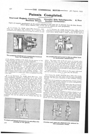
Copies of complete specifications of the patents published on this page can be obtained from the Sales Branch, Patent Office, Holborn, W.C, at the cost of sixpence for each specification, M. S. CONNER, No. 20,330, dated 30th September, 1914. When the interrupter and condenser for a magneto are mounted on the armature shaft, it is usual to connect one end
of the primary winding to the shaft, but the passage of the current through the bearings is found undesirable.
The accompanying drawing shows in section a construction by. which this difficulty is overcome. The condenser casing omthe end of the armature is lined with insulating material and the axle-end is hollow. A conducting tube is mounted inside it but insulated from it, and this tube is internally coned to take the interrupter. The other end of the tube is connected to one terminal of the primary winding. The other terminal, which is also connected to the secondary winding, is connected to a central pin which is insulated from the
inner tube. .
H. V. N. GRAVELEY, No. 15,883, dated 22nd July, 1914. This specification describes a mounting for a• side splashguard, which is designed to maintain the guard always in its correct position with respect to the road surface and the wheel, in spite of vertical and lateral movements of the I:lady:
The guard itself is hung from a bearing which rotates freely on the hub of the 'wheel, and the upper part of this bearing is connected to the body of the vehicle or to the ordinary fixed mudguard. This connection takes the form of a telescopic rod extending upwards from the bearing; the two parts of the rod can rotate relatively to one another, and a spring is mounted between them to keep them normally spaced. The upper end of this rod is pivoted to a horizontal rod which is also made in two parts and is telescopic. When the invention is applied to a non-steering wheel, the horizontal link and the spring on the vertical link may be omitted.
L. V. WARREN, No. 13882, dated 8th June, 1914.—In this carburetter an annular fuel-jet is. used. It is-constituted by a coned sleeve fitting inside a coned portion of the shell oi casing. The upper ends of the two parts are turned cylindrical so that these are the only parts requiring accurate machining to give the right dimensions for the jet. An automatic air valve is seated on top of the annular jet and is • lifted by the air suction into the mixing chamber. Provision . is made for heating the mixing -chamber by the exhaust; and two float-feed chambers are provided so that petrol or paraffin can be used alternatively.
A small auxiliary vessel is shown at the upper right-hand side for introducing a spray of water into the mixture.
R. T. PARK, No. 13,907, dated 9th June, 1914.—The accompanying drawings show this wheel with the parts dissembled and also with the parts assembled in their ordinary working position.
The outer tire is carried on a rim which has, formed integral with it, four small circular channels to receive corresponding wheels fitted with pneumatic tires. The channels are made somewhat larger than the pneumatic tires, so that contact is made only on a smelt portion of the tire, and wear is thereby prevented. These auxiliary wheels are each mounted to rotate on a spindle which is carried at one side on the brake drum and at the other side on a spider secured on the end of the axle.
When this construction is applied to driving wheels it is of particular value, as less strain occurs when starting; the general construction of the wheel is also such that the lateral stability is not sacrificed and the wheel is easily dismantled and assembled. The operation of the wheel is not affected should one of the small auxiliary tires be punctured.