 1
1 2
2 3
3 4
4 5
5 6
6 7
7 8
8 9
9 10
10 11
11 12
12 13
13 14
14 15
15 16
16 17
17 18
18 19
19 20
20 21
21 22
22 23
23 24
24 25
25 26
26 27
27 28
28 29
29 30
30 31
31 32
32 33
33 34
34 35
35 36
36 37
37 38
38 39
39 40
40 41
41 42
42 43
43 44
44 45
45 46
46 47
47 48
48 49
49 50
50 51
51 52
52 53
53 54
54 55
55 56
56 57
57 58
58 59
59 60
60 61
61 62
62 63
63 64
64 65
65 66
66 67
67 68
68 69
69 70
70 71
71 72
72 73
73 74
74 75
75 76
76 77
77 78
78 79
79 80
80 81
81 82
82 83
83 84
84 85
85 86
86 87
87 88
88 89
89 90
90 91
91 92
92 93
93 94
94 95
95 96
96 97
97 98
98 99
99 100
100 101
101 102
102 103
103 104
104 105
105 106
106 107
107 108
108 109
109 110
110 111
111 112
112 113
113 114
114 115
115 116
116 117
117 118
118 119
119 120
120 121
121 122
122 123
123 124
124 125
125 126
126 127
127 128
128 129
129 130
130 131
131 132
132 133
133 134
134 135
135 136
136 137
137 138
138 139
139 140
140 141
141 142
142 143
143 144
144 Fitters fix electrics
Page 136
Page 137
If you've noticed an error in this article please click here to report it so we can fix it.
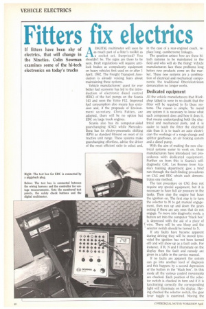
If fitters have been shy of electrics, that will change in the Nineties. Colin Sowman examines some of the hi-tech electronics on today's trucks
ADIGITAL multimeter will soon be as much part of a fitter's toolkit as a socket set. Surprised? You shouldn't be. The signs are there to be seen. Draft regulations will require antilock brakes as compulsorty equipment on heavy vehicles first used on or after 1 April, 1992. The Freight Transport Association is already voicing fears about maintaining these systems.
Vehicle manufacturers' quest for ever better fuel economy has led to the introduction of electronic diesel control (EDC) of the fuel pumps on the Scania 143 and soon the Volvo F12. Improved fuel consumption also means less emission and, if the proposals of Environment secretary, Chris Patten, are adopted, there will be no option but EDC on large truck engines.
Scania also has its computer-aided gearchanging (CAG) while MercedesBenz has its electro-pneumatic shifting (EPS) as standard fitment on most of its tractive unit range. These systems make gearchanging effortless, advise the driver of the most efficient ratio to select and, in the case of a rear-engined coach, replace long, cumbersome linkages.
The question arises: how are these hitech systems to be maintained in the field and who will do the fixing? Vehicle manufacturers face these problems long before new products come on the market. These new systems are a combination of electrical and mechanical components; the traditional fitter/electrician demarcation no longer works.
Dedicated equipment
All the vehicle manufacturers that Workshop talked to were in no doubt that the fitter will be required to fix these systems. The reason is simple. To mend any system it is necessary to know what each component does and how it does it, that means understanding both the electrical and mechanical parts, and it is easier to teach the fitter the electrical side than it is to teach an auto electrician the workings of a range-change and splitter gearboxes, an air braking system and a diesel pump.
With the aim of making the new electrical systems easier to work on, these manufacturers have introduced test procedures with dedicated equipment. Further on from this is Scania's selfdiagnostic CAC. Les Rooney from Scania's training department gave a brief run through the fault-finding procedures on CAC and EDC which each demonstrates one method.
The test procedure on CAC does not require any special equipment, but it is necessary to have full air pressure in the tanks. Then stop the engine but leave the ignition on. The first step is to turn the selector to M to get manual engagement, then run up and down the gears noting if there are any ones that do not engage. To move into diagnostic mode, a button set into the computer "black box" is depressed with the aid of a piece of wire. There will be one bleep and the selector switch should be turned to N.
If any faults have become apparent during driving they will be stored (provided the ignition has not been turned off) and will show up as a fault code. For instance. if R, N and I illuminate on the display then the fault and remedy are given in a table in the service manual.
If no faults are apparent the system can go into another level of diagnosis and this happens by a second depression of the button in the -black box". In this mode all the various control movements are checked. Each position of the selector switch is checked in turn and if it is functioning correctly the corresponding light will illuminate on the display. Having checked the selector switch, the gear lever toggle is examined. Moving the toggle to the left will bring on number two light if the circuit is functioning correctly and so on.
While in this mode the microswitch that tells the computer that the clutch pedal is depressed, is checked (number four will light up indicating that all is well). Number five should illuminate with partial accelerator depression while five and six indicate that the pedal is fully depressed.
A third depression of the button will put the system into main gearbox changing movement diagnostic mode. This checks the operation of the pneumatic cylinders that engage the gears and the confirmation switches that tell the computer when the change has taken place. The lateral stroke to the left is checked by turning the selection switch to R, when the R light should illuminate. Turning the selector to M will check the stroke to the right. Longitudinal strokes forwards and rearwards are checked using the toggle switch. When the selector switch is turned to A the neutral position is selected and four and five illuminate.
The fourth and final level of diagnostics check the range-change operation and confirmation. With the selector in N the toggle is moved to the left to check low range, and to the right to check the high range with the N and nine lights respectively indicating that all is in order. A fifth depression of the button will return the system to normal drive mode, as will turning off the key.
On electronic diesel control (EDC) there is no display save a warning light on the dash. This light comes on with the ignition and goes out when the engine is started. If during driving a fault occurs the light will come on steady for a minor problem but flashing for a major one. To carry out the full faultfinding procedure, a piece of specialised equipment is required.
The equipment is similar to that used for Mercedes-Benz EPS system and consists of what is in effect a plug with the bare end of the wires exposed. In this case the wires go into a box and are exposed via numbered holes. In addition the Scania test box has three test but tons to check safety functions — very important with a drive-by-wire system.
To start the fault-finding process the system is integrated to see whether any fault codes are stored in the memory. This is done by pressing the EDC test button on the dash and counting the number of slow flashes. It should then be pressed again; if the same number of flashes is repeated, then only one fault code is in the memory. If, for instance, there is one flash then this indicates a problem with the throttle sensor/ potentiometer. Armed with this fault code as an indication of where the problem is, the full diagnostic procedure can be gone into.
There are two types of checks carried out with the Scania test gear — one for voltage, one for impedance. All the checks for voltages are carried out with the test gear connected in between the wiring harness and the "black box", while the impedance checks just need connection to the wiring harness.
Check the voltage
With the test gear connected in between the control unit and wiring harness, the first check is the voltage between points one and 19, two and 20 and then four and 19 — all should give readings between 22 and 30 volts. So the test goes on through 16 points before moving on to the resistance tests when the control unit is disconnected. There are 24 test steps in the full procedure.
All the above checks are designed to direct the fitter to the area of the prob lem — there is no speed sensor reading, lack of a gear engagement confirmation or whatever else is shown up. But what happens then? The best advice to fitters is "Remember your basic training:" Many of the problems have a mechanical cause, but it's the electronics that show when there is a fault. If, say, the range change has siezed then the electronics will show it up as non confirmation of engagement and in doing so probably get the blame for what is a straightforward mechanical problem.
When faults do occur in these systems, their design makes fault-finding easy. But fitters will still need training in the correct way to go about it. Do not dive in without any knowledge of what you are doing, that would be a disaster — replacement units are very expensive.
Fleets running this type of hi-tech vehicle will — if they want to do servicing in-house — need to have their fitters trained and it will be reasonable to assume that the manufacturers will help. Where this help is not forthcoming, you could let the dealer do the servicing or buy a different vehicle. The second-hand value of vehicles that only the dealers can service is also questionable.
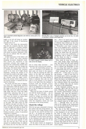
Of the imminent problems that face workshops, ABS is the one that is foremost. Workshop has already looked at the Benclix fault-finding procedure (September '89). Grau has launched a diagnostic display unit for its Category 1 ABS electronics (Skidchek) and also runs one and two-day courses for fitters at its new training centre in Blackburn. Bosch has a plug-in tester for its ABS electronics — although there are not that many in the country so far. Instructions as to its use will be given but full training is restricted to its agents.
The days of the fitter throwing his hands up in horror at anything that has a wire attached to it are over. Instead, the fitter of today must become the technician of tomorrow, and workshop managers must ensure that the necessary training takes place. If operators want to continue servicing their vehicles in-house they must act now or give up that part of the business to the manufacturers' dealers.