


A POT POURRI OF PATENTS.
Page 32
If you've noticed an error in this article please click here to report it so we can fix it.
A Re-sum.e of Recently Published Patents.
This week the patent specificationi are full of interest, so that it would be almost invidious to follow our usual plah of making a selection of some principal patent and giving but a casual reference to others.
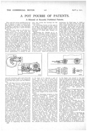
The first with which we will deal is a tractor invention. It hails from the United States, and is put forward as an improvement upon the unit-built type of tractor, in which the casing for engine, gearbox, and tranmission is made to do duty as the frame of the complete machine. No one needs to be told that the frequent disadvantage in connection with machines constructed on this principle is their inaccessibility, particularly in respect of the rear axle parts. The present invention, described by J. Rase, in specification No. 259,005, is designed to overcome this objection. The design of the tractor itself, however, as disclosed by the drawings which accompany the patent specification, is worthy of con siderable attention quite apart from the
principal feature which is the disposition of the final drive gears and the differentMl.
We will deal, however, with the latter point first. The general arrangement of the transmission is very much on the lines of the Fordsou tractor. Indeed, if we may say so, it would appear as if this tractor had been modelled on the Fordson, and was an attempt to improve upon it. There is the engine at the front, supported upon the front axle. Bolted to the engine case is the main body of the tractor, which contains the gearbox, in which the layshaft is disposed above the engine shaft. Behind the gearbox is a sleeve coupling internally splined, and so arranged that the worm shaft may be pushed into it or withdrawn therefrom with a minimum of trouble. It should be observed that the gearbox permits of a direct drive to the worm shaft. The worm wheel is above the worm, and is bolted to the differential case in the usual way. The latter is carried on ball bearings supported in brackets placed as close to the worm wheel as possible and cast in one with the rear cover to the main case. The sun wheels of the differential gear do not drive differential shafts as is generally arranged, but carry, on their extended bosses, pinions which engage with large spur wheels on the live axles. The rear coyer, tO.whith we have already referred as supporting the differential B28 case, also carries the bearings for the worm shaft.
An interesting feature of the gear is the design of change-speed forks, which are in effect box-shaped castings which partly envelop the sliding wheels, by the movement of which gear changes are effected.
Specification No. 158,984, by C. A. Cleghorn, although actnally intended to' havereference to the design of. drawbars to be used in connection with motorcardrawn caravans, is also of interest, as the principles concerned are the same as those involved when a comparatively, lightweight tractor hauls a loaded trailer or a threshing machine. The main part of the drawbar is triangular in plan, the base of the triangle being the usual hinged bar on the front of the turntable of the trailer. At its apex it is formed into a horizontal loop which is supported between a pair of coil springs attached to the tractor. Below the turntable, and to the front of it, depends a pair of struts. The lower ends of these struts are coupled to the front of the drawbar and to the axle of the turntable by adjustable tie-bars.. The inventor's claim is that, as the trailer passes over unevenness in the ground, this drawbar automatically adjusts the load on the tractor wheels. He also claims that by proper adjustment of the tie-bars it is possible to transfer a greater or less proportion of the weight of the trailer to the tractor.
Quite an interesting invention is that described by F. O'Brien. It consists of a device designed to • simplify the measurement of fuel used by a motor vehicle in travelling stated mileages. The usual fuel cap is replaced by a special one, upon which is mounted a vertical tube, which, if not of glass, is preferably so arranged that the height of the fuel can easily be ascertained. When about to make a test, the tank is filled so that the fuel rises in this small tube. If the tube is of glass, sufficient petrol should be poured in to bring the level to a mark on the tube. If not of glass, it should be filled entirely. The required mileage is then run off, and the tank replenished to the same point. The provision of this special tube not only simplifies measurement, but makes it possible to eliminate errors of observation. H. Terry and Sons, Ltd., describe in No. .158,995 an arrangement of brake
mechanism for Ford cars, in which a cable takes the place of the usual rods which couple the side lever to the rear brake shoes. At the front end the cableis provided with means of adjustment and a U-shaped clip which.couples to one of the brake levers. At the rear end: a similar clip is provided for attachment to the lever on the brake earn and the end of the cable is so attached to this clip that freedom of rotation is afforded.
In . view of the tests Which have recently taken place at Camberwell, special interest attaches to No. 159,103. which describes a form Of splashguard, ' The guard described by this invention is of the type in which a segmental plate of some flexible material is disposed near the lower edge of the wheel. In this case the flap is carried by a couple of slotted hangers, suspended from a bracket which is located on the hub of the wheel and hinged -at its rear end to a bracket on the frame. The fact that it is hinged to the frame and secured at the hub allows of the guard moving up and down with the wheel as it rises or falls under the influence of the spring. The slots are devised to 'allow of the guard itself rising and falling add moving to and fro when such movement is desirable owing to obstructions. The patentee is B. Malcolm.
A curious form of change-speed indicator is described in No. 158,93.5 by W. Chinn. A dial with four fingers is so coupled to the live axle and engine shafts that the driver can tell at a glance when his gearwheels are so running that he can engage them. There is a master finger which indicates the actual speed of the car at any time.
Specification No. .185,944, by J. H. Chandler, describes a construction of trailer for use behind either a tractor or a horse-drawn turntible. The idea is that one tractor could conveniently be used in connection with a number of such trailers, and the construction generally aims at ease of attachment and the reduction of transmission of shock from tractor to trailer.
A carburetter which is described by G. Corbett in specification No. 158,9249 is really a carburetter within a earburettor. A small compartment in the body of the main instrument is provided with the usual jet, throttle valve, etc. It would appear to be designed to provide a rich mixture in all circumstances.