


For DRIVERS, MECHANICS, & FOREMEN.
Page 31
If you've noticed an error in this article please click here to report it so we can fix it.
TEN SHILLINGS is paid to the lender of any letter which we publisls on this page, and an EXTRA FIVE SHILLINGS to the sender of the one which we select as being the best each week. All notes are edited before being published. Mention your employer's name, in confidence, as evidence of good faith. Address, A, M. and F., "The Commercial Motor," 7-15, Itosebery Avenue, London, E.G. 1.
Lamps Alight.
On Saturday, April 9th, light your lamps at 8,13 in London, 8.32 in Edinburgh, 8.23 in Newcastle, 8.28 in Liverpool, 8.21 in Birmingham, 8.23 in Bristol, and 9.11 in Dublin.
A Universal Joint Repairer.
The sender of the following cornmunicatio-n has been awarded the extra payment of b's. this week.
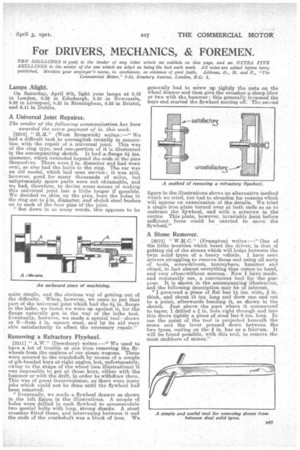
[2210] H.M." (West Bromwich) writes :—" We had a difficult task to accomplish recently in connection with the repair of a universal joint.. This was of the ring type, and onel.portion of it is illustrated in the accompanying sketch. It had a,flange 6i ins. diameter, which extended bey,ond the ends of the pins themselves. These were in. diameter and had worn oval, as also had the holes in the ring. The car was an old model, which had seen service : it was still, however, good for many thousands of miles, but unfortunately Spare parts were not obtainable, and we had, therefore, to devise some means of making this universal joint last a little longer if ppssible. We decided to skim up the pins, bore the holes in the ring out to kin. diameter, and shrink steel bushes on to each of the four pins of 'the joint.
"Set down in so many words, this appears to be
quite simple, and the obvious way of getting out of the difficulty. When, however, we came to put that part of the universal joint which had the 91 in. flange in the lathe, we found we were up against it, for the flange naturally got in the way of the lathe tool. Eventually, however, we made a special tool—shown at B—from g in. square steel, and by its aid were able satisfactorily to effect the necessary repair."
Removing a Refractory Flywheel.
[2211] " A.W." (Dewsbury) writes :—" We used to have a lot of trouble at one time removing the flywheels from the engines of our steam, wagons. These were secured to the crankshaft. by means of a couple of gib-headed keys at right angles, but, unfortunately, owing to the shape of the wheel (see illustrations) it was impossible to get at these keys, either with the hammer or with the drift, in order to withdraw them. This was of great inconvenience, as there were many jobs which could not be clone until the flywheel had been removed.
"Eventually, we made a flywheel drawer as shown in the left figure in the illustrations. A couple of holes were drilled in each flywheel to accommodate two special bolts with long, strong shanks. A stout crossbar fitted these, and intervening between it and the ends of the crankshaft was a block of iron. We generally had to se'rew up tightly the nuts on the wheel drawer and then give the crossbar a sharp blow or two with the hammer ; this generally loosened the keys and started the flywheel moving oiT. The second figure in the illustrations sb.ows an alternative method which we tried, but had to abandon for reasons which will appear on examination of the details, We tried a single iron plate turned over at both ends so as to embrace the flywheel, and with a setscrew in the centre, This" plate, however, invariably bent before sufficient force could be exerted to move the flywheel."
A Stone Remover.
[2212] " (Frampton) writes :—" One of the little troubles which beset the driver, is that of getting rid of the stones which will lodge between the twin solid tyres of a heavy vehicle, I have seen drivers struggling to remove these and using all sorts of tools, screwdrivers, tommybars, hammer and chisel, in fact almost everything that comes to hand, and very oftenzwithout SUCCegS. Now I have made, and constantly use, a convenient tool for the purpose. It is shown in the accompanying illustration, and the following description may be of interest.
" I procured a piece of flat bar l ins, wide, thick, and about 15 ins, long and drew one end out to a point, afterwards bending it, as shown in the sketch. Just abovethe part where it commenced to taper, I drilled a in. hole right through and into this drove tightly a piece of steel bar 9 ins, long. In use the point of the tool is projected beneath the stone and the lever pressed down between the two tyres, resting on the in. bar as a fulcrum. It will be found possible, with this tool, to remove the most stubborn of stones."