


OVERHAULING THE CALEDON.
Page 25
Page 26
Page 27
If you've noticed an error in this article please click here to report it so we can fix it.
No. 13.—The D and E Type 4 Ton Worm-driven and Chain-driven Chassis. Pronounced Accessibility. Complication Eschewed.
THE CALEDON chassis is too well known to the majority of our readers to need much introduction. Although the manufacture of this vehicle did not commence until 1914, it soon attained considerable popularity, and owing to its correct
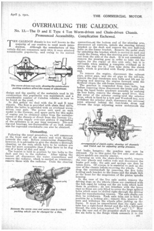
The worm-driven rear axle, showing the pointswhere packing washers afford the means of adjustment. • design and the quality of the materials used in its construction this popularity was maintained, and a considerable number of Caledon vehicles is now to be found on the road.
In this article we deal with the D and E type chassis. The first is provided with chain final drive, whilst the latter is provided with an overhead wormdriven rear axle. The power unit used on each model is the Dorman, and spare parts for this make of engine can be obtained either from the manufacturers of the chassis or direct from the Dorma.n Co., who can also supply over-size pistons if regrinding of the cylinders is at any time necessary. Die-east big-end bearings ten-thousandths of an inch undersize for reground crankshafts can also be obtained.
Dismantling.
Following the usual procedure, we will commence at the front end of the chassis and work through towards the rear. Before commencing dismantling, however, it is advisable to give the chassis a thorough cleaning, as the nuts which have to be undone are then far more accessible than if they have to be dug out of a, layer of dirt and mud.
The bonnet is held in position by two bolts to the dash and two to the radiator. After taking the bonnet off, disconnect the water connections and remove the radiator, which is carried on trunnions; remove these with the radiator. Undo the steering connectionsat the bottom end of thesteering arm, disconnect all controls, unbolt the steering column bracket on the dash and remove the two half-inch bolts on the frame bracket. Remove the pedal shaft .by unbolting the bracket which is carried at each end inside the frame, when the steering gear can be lifted oat from the side of the dash. It is not essential to remove the steering gear in order to take out the engine for the repair of this unit only, but it is advisable when making a complete overhaul as it clears the way for it. Now take down the clutch shaft, which is provided with Hardy joints at each end.
To remove the engine, disconnect the exhaust pipe, petrol pipe, and the oil pipe to the tell-tale, remove the four crankcase arm bolts and lift out by slinging and drawing the engine forward until the flywheel clears the sub-frame cross-members.
The gearbox is suspended from four bolts, but before removing these disconnect the brake pull rod, drop the hand brake quadrant assembly by undoing its four bolts, remove the change speed lever, then the cover of the selector casing: 'and the selector lever, which is fixed by a bolt and Woodruff key, now withdraw the selector shaft, disconnect the universal joint situated behind the foot-brake drum and release the large adjusting screw underneath the foot brake hangers ; the gearbox may now be released. Up to this point the live axle and chaindriven models are exactly similar. Carrying on with the chain-driven model, remove the rear wheels and radius rods and disconnect the brake pull rods; the axle and springs can then be taken down. Of course, it is essential to jack up the rear of the chassis before removing the wheels. Now drop the countershaft by removing the five bolts holding each bracket to the frame and the single Wolt at the front for the suspension of the pinion spindle housing. In the case of the live axle model, remove the driving dogs on the wheels (these are combined with the hub caps) by taking out the six bolts which hold them in position ; do not interfere with the brass caps as these are only fitted to cover the large splined holes which must be drilled right through the driving dogs for manufacturing reasons. The axle shafts can then be withdrawn. Each axle tube nut is held in position by a locking pin ; remove this, unscrew the nuts and withdraw the wheels after jacking up the frame. It must be remembered that the right axle tube has a. right-hand thread and the left a left-hand thread, the nuts being marked "R" and " L." Now drop the rear end of the propeller shaft by removing the six bolts in the flange which connects it to the worm shaft ; disconnect the brake pull rods, remove the four spring clips which bind the axle to the springs, and lift; out the axle. Next take off the split-pinned collars on the front spring bar and rear shackle bar, and after taking off the spring clips draw the springs off sideways until clear. If, for any reason, it is necessary to inspect the rear axle of the live axle model whilst on the road or elsewhere, the worm gear and differential unit can be withdrawn by taking off the driving hub caps and withdrawing the differential shafts until they are clear of the differential. The countershaft of the chain-driven model is designed with a similar end in view. The sprockets can be left in position and the differential sh af t s withdrawn.
Overhauling the Engine.
Remove the exhaust manifold and the combined inlet, manifold and water connection, then the valves and their tappets ; t h e latter are held down in pairs by bridge pieces, each of which has a central stud. Now lift the cylinders and turn the whole engine upside down in order to remove the sump. Undo the big-end bolts and lift out the pistons and connecting rods. The oil pump is driven by skew gearing from the camshaft, and great care should be taken with the driving rod. This is on a square at each end, and it is quite possible to leave one end free when erecting the engine, with the result that seizure of the engine would almost certainly occur.
There is a ball thrust washer at the front end of the crankshaft behind the timing wheel. This may require the addition of thin washers to take up end play. The camshaft is carried in phosphorbronze bushes, the centre bush, which takes the thrust in each
direction, being locked by a setscrew. The governor shaft runs in plain phosphor-bronze bushes ; any end play can be taken up by thin washers. Sometimes these are -positioned at the outside but this is bad practice and should not be followed! All the timing wheels are drilled and tapped 0 in. Whitworth for the bolts of a crossbar extractor.
When erecting the engine care should be taken to see that the oil level gauge pin is centred into its hole, otherwise the end may float up inside the crankcase instead of rising through it. All the oil pipes in the engine should have paraffin squirted through them by means of a syringe. The main bearings and big-ends are of die-cast white metal, and solid brass shims are employe d. The valve guides can be taken out when worn, new guides being drawn into position by means of a bolt and nut. The clutch cone is Ferodo lined, the centre being bushed for the crankshaft end. The lubricating passage has two bends and should be Well cleaned out during overhaul. The clutch spring is provided with a ball thrust washer at its rear end, this being held by a Vislok nut. To remove the spring, the twothalves of the nut must be brought into line, when it can be unscrewed; this also applies to spring adjustments.
Overhauling the Gearbox.
To dismantle the gearbox, first remove the reverse shaft, which is at the top, then unscrew the locking plunger spring caps and the locking calliper at the end of the gearbox extension arm, unscrewing the bolt of the calliper from the back of the casing. 'Remove the three nuts of the selector rods and take off the selector forks. Next remove the rear guide blockfor the selector rods and the extension arm; which leaves the selector rods loose, and they can be withdrawn.
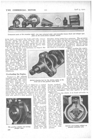
The driving spider at the front end of the main shaft must now be withdrawn, and one of our innstrillions shows the device used for this purpose. Behind the driving spider is a housing which 6an be taken off by unscrewing its four nuts. This housing comes away complete with the main shaft ball race. Behind this ball race is a bush which is a sliding fit in the pinion and is held by four setscrews. This bush must be pulled out, and the shaft can then be removed. When refitting, care • should be taken to wire the heads of the setscrews tagether again. The housing at the other side is removed in the same manner, except that there is no bush in this instance.
To remove the laysh aft, take off the caps at each end, and then the nuts on the shaft, . when the latter can be tapped through in either direction, bringing with it the 'ball races. The . small fixed pinion is on splines and can be slipped off. Then draw the shaft right out, letting the two sliding wheels remain in the box and leaving the larger fixed pinion on the shaft.
The only repairs likely to be needed are replacements of the ball races, the bushes in the sliding pinions on the Iayshaft and those in the reverse pinion. Occasionally the locking plunger springs become weak or clogged up, and they must then be cleaned out or replaced as the case may be. In each of the hall race housings is a V-shaped felt washer and gland nut ; if much worn, these washers may require renewal, although it mayOnly be necessary to screw up the gland nuts, which, incidentally, a r e held in position by. locking plates.
The Rear Axle.
At each side of the differential ea.sing is a. ball thrust washer, and the worm -wheel is centred by the insertion of packing washers of 20 SAV.G. steel at the outer ends of the thrust washers. three or more being utilized according to the requirements. Each half of the differential easing is provided with two tapped
holes to assist in withdrawing it from the recess in the warm wheel, into which it _fits tightly. The worm shaft has a double ball thrust race at its rear end, and any end play can be taken up by removing the split-pin of the locking nut, tightening up the latter and repinning.
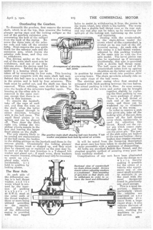
Dealing with the countershaft, -in the chain-driven model the crown wheel of the conntershaft is riveted on to one half of the differential easing. At each side of this casing is a ball thrust washer, adjusted by thin packing washers in the same way as with the live axle model. The bevel pinion can also be washered up if necessary (incidentally, this also is ,provided with a double ball thrust race). The ball races at the end of the countershaft tubes butt op against
shoulders on the latter and are held in position by round nuts wired into position after screwing home. The chain sprockets actually ride on the outer rings of the ball races.
The steering gear casing when first erected is arranged with thick packing between the two halves. The actual packing is 3-32 in. fibre. As wear occurs, the centres of the worm and sector can be brought together slightly by replacing the fibre packing by one or more paekings of paper. There is a ball thrust at each end of the steering worm, and these can be washered up to eliminate end play in the worm. In order to remove a stub wile pivot pin, take off the locking wire of the nut, then screw off the. ball thrust cover which, incidentally, is used for adjusting this thrust. Knock out the cotter pin which comes right thrsugh the axle, and tap out the pivot pin.' The jaws of the stub axles are bushed at the top and bottom ; these bushes may require renewal. It will be noted from the foregoing description that great care has been taken to rendeisparts liable to wear accessible with a minitritun of dismantling. All bolts are standard British:fine thread, and the simplest possible method of securing every part has been carefully studied.
Complications of any sort have been eliminated from the design as a w h o 1 e, thereby making it possible for the owner of a vehicle who experiences any of the usual small troubles to maintain it on the road with the
Sectional view of countershaft on chain-driven model. Arrows denote where adjusting washers ire positioned. Note mounting of sprockets so that shafts can he withdrawn in order to iemove the bevel and differential
usual s;.quipment found in practically any small garage. TbiS is a most im
portant feature, particularly where the vehicles are employed at a n y 'ecinsiderable d i stance from a large repair shop; it also reduces thetcost of vehicle maintenance, enabling the machines to give full service.