


Perkins apply charge cooling to turbocharged 1.254
Page 66
Page 67
Page 68
If you've noticed an error in this article please click here to report it so we can fix it.
by Paul Brockington,
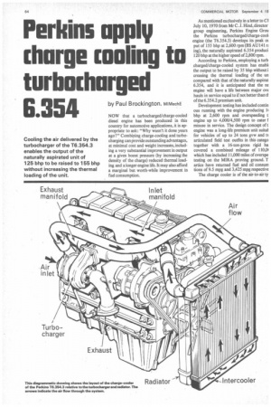
MIMechE NOW that a turbocharged/charge-cooled diesel engine has been produced in this country for automotive applications, it is appropriate to ask: "Why wasn't it done years ago?" Combining charge-cooling and turbocharging can provide outstanding advantages, at minimal cost and weight increases, including a very substantial improvement in output at a given boost pressure (by increasing the density of the charge) reduced thermal loading and a longer engine life. It may also afford a marginal but worth-while improvement in fuel consumption. As mentioned exclusively in a letter to CA July 10, 1970 from Mr C. J. Hind, director group engineering, Perkins Engine Grou the Perkins turbocharged/charge-cool engine (the T6.354.3) develops its peak ot put of 155 bhp at 2,600 rpm (BS AU14 I n ing), the naturally aspirated 6.354 produci 120 bhp at the higher speed of 2,800 rpm.
According to Perkins, employing a turb charged/charge-cooled system has enabll the output to be raised by 35 bhp without i creasing the thermal loading of the un compared with that of the naturally aspirat 6.354, and it is anticipated that the ne engine will have a life between major ow hauls in service equal to if not better than ti of the 6.354.2 premium unit.
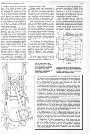
Development testing has included contin ous running with the engine producing 1 bhp at 2,600 rpm and overspeeding t engine up to 4,000/4,500 rpm to cater misuse in service. The design concept oft engine was a long-life premium unit suitat for vehicles of up to 24 tons gvw and ts articulated field test outfits in this catego together with a 16-ton-gross rigid ha covered a combined mileage of 110,01 which has included 11,000 miles of overspe testing on the MIRA proving ground. T artics have returned fuel and oil consum tions of 9.5 mpg and 3,425 mpg respective The charge cooler is of the air-to-air ty id is mounted in front of the jacket-water idiator where cooling is assisted by the idiator fan. It weighs 25Ib and is made by rck Radiators Ltd, Birmingham, a firm hich has had long experience in producing r-to-air as well as water/air coolers for Ldustrial engines (and water/air types for Larine units) and corroborates the Perkins aim that charge cooling gives a big reducan in thermal loading. A short appraisal of tercooling and historical backgrounds ssed on the views of Serck technicians is [yen elsewhere in this issue.
Although the T6.354.3 is dimensionally milar to the 6.354/ diesel with the same optimum" bore and stroke of 3.875in. )8.4mm) by 5.0in. (127.0mm), it is virtually new engine. Later in 1971 it will be offered s a turbocharged engine producing 138 bhp 2,600 rpm as well as a turbocharged/ large-cooled unit, to cater for vehicle manuicturers who require a lower output. But Mr Lind is confident that the T6.354.3 will have [yen such a good account of itself by that me that no one will require a non-charge›oled version.
Maximum torque of the unit of 376Ib ft ;2kgm) is produced at 1,600 rpm while the can piston speed is 2,166ft/m (11m/sec). he compression ratio is about 154 to 1 and le dry weight of the bare engine is 912% 112kgm). A naturally aspirated equivalent 8201b, the charge-cooler accounting for 25% of the difference in weight.
Full-load specific fuel consumption is 0.37Ib bhp/h at the maximum-torque speed and 0.41b bhp/h at maximum speed which correspond to the consumptions of the naturally aspirated unit. It is anticipated that more favourable fuel consumptions in mpg will be obtained in service compared with a naturally aspirated unit of the same output.
Other special features of the T6.354.3 include oil-cooled pistons designed to reduce the temperature of the ring-belt in addition to the crown, a stiffened crankcase structure that assists in reducing the noise level of the unit, and a redesigned jacket-cooling system that promotes uniform cooling of the cylinder head and block. Detail improvements include a laminated steel-and-copper cylinder head gasket and a Ringfeder locking system that simplifies locking the crankshaft pulley in place.
The turbocharger is a Hoiset 3LD twinentry model. At an ambient air temperature of 80deg F (26.7deg C) and a turbocharger entry temperature of 120deg F (49deg C) the temperature of the outlet air at peak output without a charge-cooler would be around 250deg F (121deg C) which represents a temperature difference of 130deg F (72deg C).
The charge-cooler reduces the temperature of the air to 140deg F (60deg C) and the temperature difference to 20deg F (1 ldeg C). The cooler can, therefore, be credited with a reduction in temperature of 110deg F (61deg C) and a corresponding reduction in the temperature of the air in the cylinder at the time the inlet valve closes. In the case of a turbocharged non-charge-cooled unit this would be about 300deg F (149deg C).
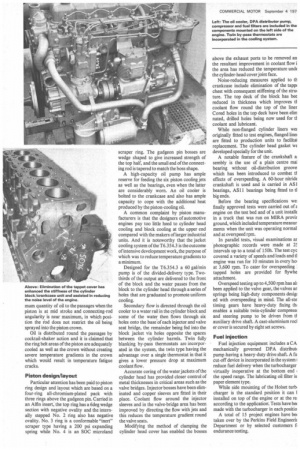
Wellworthy pistons are used which have annular oil-cooling passages above the gudgeon pin bosses (produced by the solublecore method) the open ends of the passages being fed with oil from a jet located at the base of each cylinder on the thrust side. Oil is continuously discharged from the jets and the system is designed to supply the maxi mum quantity of oil to the passages when the piston is at mid stroke and connecting-rod angularity is near maximum, in which position the iod does not restrict the oil being sprayed into the piston crown.
Oil is distributed round the passages by cocktail-shaker action and it is claimed that the ring belt areas of the piston are adequately cooled as well as the crown without creating severe temperature gradients in the crown which would result in temperature fatigue cracks.
Piston design/layout
Particular attention has been paid to piston ring design and layout which are based on a four-ring all-chromium-plated pack with three rings above the gudgeon pin. Carried in an Alfin insert, the top ring has a 6deg wedge section with negative ovality and the internally stepped No. 2 ring also has negative ovality. No. 3 ring is a conformable "inert" scraper type having a 200 psi expanding spring while No. 4 is an SOC microland scraper ring. The gudgeon pin bosses are wedge shaped to give increased strength of the top half, and the small end of the connecting rod is tapered to match the boss shape.
A high-capacity oil pump has ample reserve for feeding the six piston cooling jets as well as the bearings, even when the latter are considerably worn. An oil cooler is bolted to the crankcase and also has ample capacity to cope with the additional heat produced by the piston-cooling oil.
A common complaint by piston manufacturers is that the designers of automotive engines pay too little heed to cylinder head cooling and block cooling at the upper end compared with the makers of larger industrial units. And it is noteworthy that the jacket cooling system of the T6.354.3 is the outcome of intensive development work, the purpose of which was to reduce temperature gradients to a minimum.
Designed for the T6.354.3 a 60 gal/min pump is of the divided-delivery type. Twothirds of the output are delivered to the front of the block and the water passes from the block to the cylinder head through a series of holes that are graduated to promote uniform cooling.
Secondary flow is directed through the oil cooler to a water rail in the cylinder block and some of the water then flows through six holes onto the base.of each injector and valve seat bridge, the remainder being fed into the block jacket via holes opposite the spaces between the cylinder barrels. Twin fully blanking by-pass thermostats are incorporated in the system, the twin type having the advantage over a single thermostat in that it gives a lower pressure drop at maximum coolant flow.
Accurate coring of the water jackets of the cylinder head has provided closer control of metal thicknesses in critical areas such as the valve bridges. Injector bosses have been eliminated and copper sleeves are fitted in their place. Coolant flow around the injector sleeves and in the valve-bridge area has been improved by directing the flow with jets and this reduces the temperature gradient round the valve seats.
Modifying the method of clamping the cylinder head cover has enabled the bosses above the exhaust ports to be removed an the resultant improvement in coolant flow i the area has reduced the temperature uncle the cylinder-head cover joint face.
Noise-reducing measures applied to th crankcase include elimination of the tapp( chest with consequent stiffening of the stru( ture. The top deck of the block has bee reduced in thickness which improves ti coolant flow round the top of the liner Cored holes in the top deck have been elim nated, drilled holes being now used for tt coolant and lubricant.
While non-flanged cylinder liners wer originally fitted to test engines, flanged linei are fitted to production units to facilital replacement. The cylinder head gasket ws developed specially for the unit.
A notable feature of the crankshaft a: sembly is the use of a plain centre mai bearing without oil-distribution groove which has been introduced to combat tt effects of overspeeding. A 60-hour nitride crankshaft is used and is carried in AS1 bearings, AS11 bearings being fitted to ti big ends.
Before the bearing specifications wei finally approved tests were carried out of a engine on the test bed and of a unit installe in a truck that was run on MIRA provir ground, which included temperature measur ments when the unit was operating normal and at overspeed rpm.
In parallel tests, visual examinations ax photographic records were made at 2.! intervals up to a total of 150h. The test cyc covered a variety of speeds and loads and ti engine was run for 10 minutes in every ho' at 3,600 rpm. To cater for overspeeding tapped holes are provided for flywhe attachment.
Overspeed testing up to 4,500 rpm has al( been applied to the valve gear, the valves an springs being high-duty components desigi ecl with overspeeding in mind. The all-ste timing gears have heavy-duty fixing th; enables a suitable twin-cylinder compress( and steering pump to be driven from ti auxiliary drive shaft. A cast-aluminium rod er cover is secured by eight set screws.
Fuel injection Fuel injection equipment includes a CA mechanically governed DPA distribut( pump having a heavy-duty drive shaft A fu cut-off device is incorporated in the system I reduce fuel delivery when the turbocharger virtually inoperative at the bottom end the speed range. The lubricating oil filter is paper element type.
While side mounting of the Holset turb, charger is the standard position it can installed on top of the engine or at the re. according to the application: Tests have be( made with the turbocharger in each positio A total of 15 project engines have be taken over by the Perkins Field Engineerir Department or by selected customers fi endurance testing.