Cummins V6 at Rear on Na laimier Single-decker
Page 70

Page 71

Page 72

If you've noticed an error in this article please click here to report it so we can fix it.
SINGLE-DECK passenger chassis employing a
. Curtin-tins V6 engine vertically mounted at the
extreme rear of the chassis has been announced by Transport Vehicles (Daimler) Ltd. Daimler, of course, already make a rear-engined double-decker—the Fleetline —and it will be remembered that at the 1962 Commercial Motor Show the concern featured a prototype singledecker With its Daimler engine located below frame level at the rear. It is now apparent that the chassis was part of an exercise to assess the possible demand for a single-deck passenger vehicle with this engine position. Having become satisfied on this point, Daimler has selected the Cummins V diesel as being most suitable for use in the model because its compact overall length of only 33-5 in. allows it to be mounted vertically, the prOtrusion above the rear frame not affecting the body floor level as it is short enough and low enough to be accommodated under the contour of a fullwidth passenger seat at the rear of the body.. The designation given to the model is Roadliner. The chassis is suitable for both bus and coach bodies, although alternative engine power ratings and rear axles are offered to meet the particular needs of the two types of use. There is no difference in the chassis frame for bus and coach bodies. The two sidemembers are channel
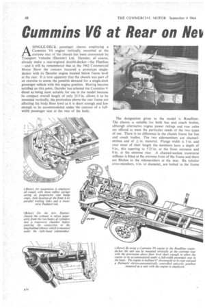
section and of in. material. Flange width is 3 in. and over most of their length the members have a depth of 9 in., this tapering to 5-25 in. at the front entrance and 8 in. at the extreme rear. A channel-section transverse stiffener is fitted at the extreme front of the frame and there are flitches in the sidemennbers at the rear. Six tubular cross-members, 4 in, in diameter, are bolted to the frame
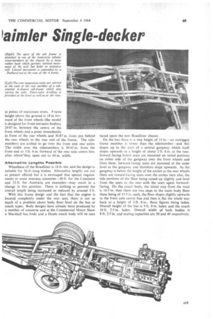
at points of maximum stress. Frame height above the ground is 18 in forward of the front wheels (the model is designed for front-entrance bodies), 24-87 in. between the centres of the front wheels and a point immediately in front of the rear wheels and 30-87 in. from just behind the rear wheels to the rear end of the frame. The sidemembers are arched to go over the front and rear axles. The width over the sidemembers is 30-43 in, from the front end to 3 ft. 6 in. forward of the rear axle centre line, after whichlhey open out to 44 in. width.
Alternative Lengths Possible Wheelbase of the Roadliner is 18 ft. 6in. and the design is suitable for 36-ft.-long bodies. Alternative lengths are not at present offered but it is envisaged that special requirements in some overseas countries-40 ft. for the Continent and 33 ft. for Australia are examples—may result in a change in this position. There is nothing to prevent the overall length being increased or reduced by around 3 ft. 'With this frame design and the fact that the engine is located completely under the rear seat, there is not so much of a problem about body floor level on the bus or coach types. Body designs have already been produced by a number of concerns and at the Commercial Motor Show a Marshall bus body and a Duple coach body will be seen based upon the new Roadliner chassis.
On the bus there is a step height of 15 in.—an outrigged frame member is lower than the sidemember—and this slopes up to the start of a central gangway which itself slopes upwards to a height of about 2 ft. 8 in. at the rear. Inward facing bench seats are mounted on raised portions on either side of the gangway over the front wheels and from these, forward-facing. seats are mounted at the same level as the gangway and therefore slope upwards. As the gangway is below the height of the arches at the rear wheels there are inward-facing seats over the arches here also, the side portions of the floor being raised up slightly and level from the seats to the rear with the seats again forwardfacing. On the coach body, the initial step from the road is 16.5 in. then there are two steps to the main body floor these being of 11.5 in. each, the floor slopes slightly upwards to the,front axle centre line and then is flat the whole way back at a height of 3 ft. 8 in., these figures .being laden. Overall height of the bus is 9 ft. 8 in. laden and the coach 10 ft. 2.5 in. laden. Overall width of both bodies is 8 ft. 2.5 in. and seating capacities are 50 and 49 respectively.
The Cummins V6 used M the chassis has a capacity of 9-63 litres (588 Cu. in.) and in its maximum rated form produces a maximum of 192 b.h.p. net at .2,600 r.p.m. and a maximum net torque of 433 lb. ft. at 1,700 r.p.m. This version of the engine is intended for coach applications. For bus use the engine is derated—both in fuel delivery and maximum speed-and produces a maximum of 150 b.h.p. net at 2,100 r.p.m. and a maximum net torque of 405 lb. ft. at 1,200 r.p.m.
The engine is inclined dOwnwards towards the rear axle at an angle of 40 to the horizontal and is mounted at four points—two at the front and two at the rear—all mountings being rubber/steel units, the two at the front being of the compressed-shear type. The rear ones are of V-block type.
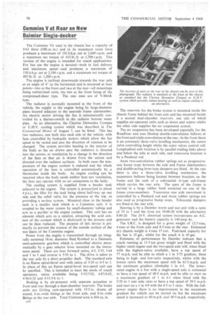
The radiator is normally mounted at the front of the vehicle, the supply to the engine being by large-diameter pipes located adjacent to the nearside frame sidemember. An electric motor driving the fan is automatically controlled by a thermo-switch in the radiator bottom water pipe. As an alternative, the Clayton Dewandre Compas or U.H.V. cooling system which was described in The Commercial Motor of August 7, can be fitted. This has two radiators, one built into each side of the vehicle, with fans controlled by hydraulic motors which allow the fan speed to be varied and also the direction of rotation to be changed. The system provides heating to the interior of the body as the air drawn past the radiators is directed into the saloon, or ventilation by a change in the direction of the fans so that air is drawn from the saloon and directed over the radiator surfaces. In both cases the temperature of the engine coolant is reduced and the whole operation of the fans is controlled automatically by a thermostat inside the body. As engine cooling can be required when the body needs neither heat nor ventilation, the fans can operate with no air connection to the body.
The cooling system is supplied from a header tank adjacent to the engine. The system is pressurized to about 4 p.s.i., the filler for the tank being about half-way up one side and the relief valve for the pressure at the top, so providing a no-loss system. Mounted .close to the header tank. is a smaller tank which is a Cummins unit; it is coupled to the water system by small-diameter tubing and acts as a purifier to the engine coolant. This unit has an element which acts as a catalyst, attracting the acid content of the coolant which is destroyed in the process and can be then replaced. The purpose of this device is primarily to prevent the erosion of the outside surface of the wet liners of the Cummins engine.
Power from the engine is transmitted through an integrally mounted 18-in. diameter fluid flywheel to a Daimatic semi-automatic gearbox which is controlled electro pneumatically by a gear selector lever mounted on the instrument panel. There are four forward ratios, 4.5, 2.53, 1.64 and 1 to I and reverse is 5-53 to 1. The drive is taken to the rear axle by a short propeller shaft. The standard axle is an Eaton spiral-bevel unit with ratios of 5.29 or 6.5 to 1. In place of this an Eaton spiral-bevel two-speed unit can be specified. This is intended to meet the needs of coach operators, ratios available -being 515/7-02, 487/665,, 4.56/6.22 and 4.11/5.6 to I.
Braking is by air-pressure with separate actuation to front and rear through a dual-chamber reservoir. The brake units are Girling cam-operated with 15.5 in. drums all round, 6-in.-wide linings at the front axle, and 8-in.-wide linings at the rear axle. Total frictional area is 844 sq. in.
E16'
The reservoir for the brake system is mounted inside the chassis frame behind the front axle and has mounted beside it a second dual-chamber reservoir, one side of which supplies air-operated units such as doors and wipers whilst the other side supplies the air suspension system.
The air suspension has been developed especially for the Roadliner and uses Dunlop double-convolution bellows at the front and triple-convolution at the rear. At the front there is an automatic three-valve levelling mechanism, the centre valve controlling height whilst the outer valves control roll. Longitudinal axle location is by parallel trailing links above and below the axle at each side, and transverse location is by a Panhard rod.
Aeon two-convolution rubber springs act as progressiverate bump stops between the axle and frame sidemembers and double-acting lever-type dampers are fitted. At the rear there is also a three-valve levelling mechanism, the suspension bellows being located between brackets on the frame and the ends of a substantial A-type sub-frame which carries the rear axle. The apex of the frame is carried in a large rubber bush mounted on one of the frame cross-members. Transverse rear axle movement is controlled by a Panhard rod and Aeon rubber springs are also used as progressive bump stops. Telescopic dampers are fitted at the rear axle.
Steering is by a Daimler worm and nut unit with a ratio of 33 to 1 and the tyres are 10.00-20 with the alternative 9.00-20. The 24 V. electrical system incorporates an A.C. generator and the battery capacity is 140 amp. hr.
The S.R.C. is designed for a gross weight of 12.5 tons, 4 tons at the front axle and 8.5 tons at the rear. Estimated dry chassis weight is 4 tons 17 cwt. Fuel-tank capacity for the bus is 35 gal., whilst for the coach it is 45 gal.
Estimates of performance by Daimler indicate that a coach running at 11-5 ton gross weight and fitted with the higher rated engine and the two-speed axle will, when fitted with the highest-ratios available, have a top speed of 77 m.p.h. and be able to climb a 1 in 5.75 gradient, these being in highand low-ratio respectively, whilst with the lowest ratios the maximum speed will be 61.5 m.p.h. and the maximum gradient climbable I in 4.5. The lowerrated engine in a bus with a single-speed axle is estimated to have a top speed of 48-5 m.p.h. and be able to start on a maximum gradient of 1 in 61 when fitted with the . 5.29 to 1 rear axle ratio or have a top speed of 39.5 m.p.h.
and start on a 1 in 4.9 with the 6.5 to 1 ratio. With the fullpower engine there is no improvement in the maximum gradient the vehicle can be started on but the maximum speed is increased to 60 m.p.h. and 48.5 m.p.h. respectively.


