


Self-adjusting Rubber Springs
Page 82
If you've noticed an error in this article please click here to report it so we can fix it.
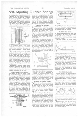
AN independent suspension system with rubber as the resilient medium is shown in patent No. 814,290. Although illustrated as applied to a vehicle with a central backbone-type frame, it can also be used with those based on a conventional chassis. (Delta Motor Research, Ltd., Potton Manor, Potton, Beds.)The drawing shows the seheme aPplied
to a non-driven wheel. The centra tubular backbone (1) carries a bracket to which is fixed a cylinder (2), whilst the stub axle is attached to a central spindle (3).
The spindle carries vanes (4) which interleave with inwardly projecting vanes on the cylinder, and rubber is interposed between the two sets to act as a spring. Another layout described employs serrated inner and outer cylinders with a rubber sleeve gripped between the serrations. On a driven Wheel, two sets of springs, one above the other, would be used, and the driving axle would pass between them.
Each spring is provided with an adjusting device to pre-load the rubber and on a heavy vehicle this would be servooperated from the cab, so that adjustment could be effected to suit the load.
PETROL INJECTION SYSTEM
PATENT No. 814,164 shows a distributor for a petrol injection system. At low engine speed the distributor supplies timed spurts. one to each cylinder, but -above a certain -speed, a continuous' flow is provided. (General Motors Corporation, Detroit, Michigan, U.S.A.)
The drawing shows a section of a distributor for an eight-cylindered engine. The fuel is supplied under pressure from an engine-driven pump and enters through the port (1). It flows through a port (2) in a rotary cone-valve and passing up the central bore is distributed by the radial port (3) to the various outlets (4).
Normally, the cone-valve is held on to its seat by a spring (5), but as the engine speed rises, so does the pressure from the supply pump. This ultimately becomes high enough to lift the cone from its seating and cause fuel to be discharged from all the outlets together. A sliding coupling (A) in the drive spindle permits the valve to rise without loss of drive.
AIR-COOLED DAMPER
A TORSIONAL vibration damper t A-generates heat, and, if the damper incorporates rubber, a temperature rise
: can affect the spring rate. Patent No. 814,062 shows a damper incorporating air cooling, intended for mounting • on the crankshaft of an engine, close to the pulleys for driving auxiliaries. (Holset Engineering Co., Ltd., Turnbridge, Huddersfield.) .
Referring to the drawing, the hub (I) is fixed to the crankshaft and spokes (2) carry the pulleys(3). The. damper comprises a rim (4) carrying an inertia ring (5) with a rubber ring (6) interposed. The inner rim is supported upon a number of thin radial vanes (7) which act not only as spokes but also function as a centrifugal fan, circulating cooling air through the assembly. External vanes (8) assist this action.
MAINTAINING TYRE PRESSURE
PATENT No. 814,371 describes an annular air reservoir for fitting to the rim of a tyred wheel. Air under high pressure is stored, and fed to the tyre as required by a constant-pressure valve. The patent comes from A. Morrison, 68 Dundrennan Road, Glasgow, S.2.
FITTING TUBELESS TYRES
QNE of the problems encountered in fitting tubeless tyres is that of sealing the bead to the rim before the inflation pressure is high enough to do it. A device to obviate this is the subject of patent No. 814.172. (Dunlop Rubber Co., Ltd., 1 Albany Street, London, N.W.1.)
The tyre is first placed on the rim and then the assembly is inserted into the machine shown in the drawing. A circular upper plate (I) is provided with a knifeedged rim (2) which engages with the side wall of the tyre when the assembly is 'pressed upwards by an hydraulic cylinder (3). This makes an airtight joint at the edge. To close the central hole in the wheel, a rubber-faced disc (4) comes into sealing contact with the face of the rim.
Air can now be pumped in via the inlet (5) to inflate the tyre. Once air pressure has forced the upper bead against the rim, the assembly is self-sealing and can be removed from the machine.
SLIDING BUS DOOR
AA REAR sliding door for buses and coaches is the subject of patent No. 813,272. (A. Alcock and East Lancashire Coachbuilders, Ltd., New Whalley Road, Blackburn, Lancs.)
The door, which is of double width, is hinged in the middle and controlled in its path by curved guideways so that it forms a right-angle when open. .
The drawing is a plan of the door, showing two parts (I and 2) in the closed position. When slid to the left to open it, rollers (3) traverse a curved guide (4) and finish at the point (5).
The door is then open, and occupies the position shown in chain lines at 6. The patent describes also an electric motor drive for operating the door. References are made to an earlier patent numbered 771,672.
TRACTOR STABILITY
PATENT No. 813.704 shows a scheme for overcoming stability problems with short-wheelbase four-wheeled earthmoving equipment. (Socidt6 Auxiliare de L'Enterprise Auxen, 15 rue de Lubeck, Paris.)
The drawing shows a vehicle modified according to the invention. An extra wheel (1) is carried on a hydraulically operated linkage (2) and can be lowered o the ground when the machine is at work, thus increasing the effective wheelbase.
When travelling light, the extra wheel can be raised clear of the ground. Another scheme shows the support wheel combined with and acting as a carrier for a scraper blade (3).