


Patents Completed.
Page 24
If you've noticed an error in this article please click here to report it so we can fix it.
Complete specifications of the following patents will be sent to any address in the United Kingdom by the Sale Branch, Patent Office, Holborn, W.C., upon receipt of eightpence per copy.
Adjustable Steering Gear.
Soc. Anon. des Automailes et Cycles Peugeot, No. 3268/13, dated under International Convention 10th February, 1912.
—This invention has for its object the construction of an efficient steering gear, and combines means for compensating for the wear between the worm and worm segment.; means arc also provided for adjusting the inclination of the steering pillar. The gear is enclosed in a casing composed of three distinct parts ; the part enclosing the worm is semicircular in cross-section and is provided on its lower side with facings, between which and the other portions of the casing, are fitted the adjustment strips. When wear occurs between the worm and worm segment it is only necessary to replace the strips by thinner ones to compensate for the wear and bring the gears together again. Half of the casing enclosing the worm segment is provided with a tapered extension which fits into a similarly formed hole in a portion of the frame of the vehicle. The end of this conical portion is provided with a screw thread on which are mounted two nuts. This construction allows for altering the inclination of the steering pillar. The worm is mounted on ball bearings at both ends within its casing, thus forming easy-running thrust members.
Pressed-Steel) Connecting-Rods.
W. L. Spence, No. 25,813, dated 11th November, 1912.—This specification describes a method of constructing connect
the rod is a tapered tube of oval section, and an oil duct may be provided in it by forming a cavity along one of the overlapping edges. The small-end is a corrugated pressing, which is bent round to enclose the end of the main tube and welded to it. A second tube is inserted transversely to receive the white-metal lining. The big-end is built up of two parts, one of them being provided with a spigot to enter the •end of the oval tube and to be welded to it, and the other part is similar in shape to an ordinaly marine type of big-end, but is stiffened with ribs or corrugations, pockets being formed therein to receive the big-end bolts. A second pressed steel shell, which is also ribbed, fits inside the first and closes the end of the tube forming the rod. All these parts are preferably welded together, a third sleeve being inserted to carry the white-metal lining. The various components used in building up this connecting-rod are designed with the view to being consolidated by the welding process.
Fuel-Supply System.
W. Richardson and S. Hughes, N. 18,930, dated 19th of August, 1912.—This invention consists of a combined pressure and gravity feed to the carburetter. A pipe is led from the main pressure petrol tank to a small tank situated above the
carburetter. This tank consists of a cylindrical chamber provided with a pipe passing through its centre nearly to the top, the pipe being led from the pressure tank. A float-valve is arranged to close the top of the central pipe when the chamber is full ; the top of the chamber is provided with a screwed cover and communicates with the atmosphere by means of a series of holes. This prevents any possibility of a vacuum occurring in the chamber. A pipe is connected from the bottom uf the chamber to the carburetter. It will be seen that oil flowing under pressure from the main tank will fill the chamber until it reaches the level at which the float works ; the valve will then close and cut off the supply, the carburetter drawing fuel from the auxiliary chamber ; as the level decreases an the valve will open and allow more oil to enter under pressure, the oil being thus kept at a constant level. The chamber contains sufficient fuel to enable the engine to be started up and run for some miles in case of tank leakage. Motor Stretcher Carrier.
P. Lemaistre, No. 8053/13, dated under International Convention 12th July, 1912.—According to this invention any motor vehicle can be quickly converted into an ambulance wagon. It consists in providing a framework which is attached to the chassis of the motor by suitable.stirrups. This framework is adapted to hold stretchers, and in order that these may be placed in the carrier with ease, the framework is provided with rails on which to run trollies, these trollies being attached to the stretchers. The stretchers can therefore he run into the framework quite easily.
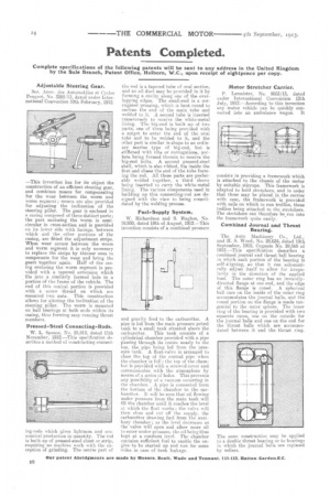
Combined Journal and Thrust Bearing.
The Auto Machinery Co., Ltd., and H. S. Wood, No. 20,624, dated 10th September, 1912, Cognate No. 29,565 of 1912.—This specification describes a combined journal and thrust ball bearing in which each portion of the bearing is self-aligning, so that it can automaticallyadjust itself to allow for irregularity in the direction of the applied load. The outer ring has an inwardlydirected flange at one end, and the edge of this flange is coned. A spherical ball race on the inside of the outer ring accommodates the journal balls, and the coned portion on the flange is made tangential to the outer sphere. The inner ring of the bearing is provided with two separate races, one on the outside for the journal balls and one on the end for the thrust balls which are accommodated between it and the thrust ring.