


A New Design of Moving Floor
Page 48
If you've noticed an error in this article please click here to report it so we can fix it.
A Risme' of Recently Published Patent Specifications
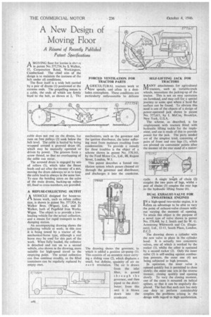
MOVING floor for lorries is sho.-vn in patent No. 577,734, by S. Walker, 37, Corporation Road, Workington, Cumberland. The chief aim of the design is to maintain the tautness of the belt under all conditions.
The floor itself is a wide belt carried by a pair of drums (I) positioned at the extreme ends. The propelling means is a cable, the ends of which are firmly fixed to the bell, as shown at 2, Thc
cable does not rest on the drums, but runs on free pulleys (3) sunk below the belt level. The cable is hauled by being wrapped around a grooved drum (4), which may be manually operated or driven by power. The grooves form a screw thread, so that no overlapping of the cable can occur.
The screwed drum is engaged by sets of rollers (5), which take the thrust loads and act after the manner of a nut, moving the drum sideways so as to keep the cable lead-in always in the same line. To ease the bending stress on the axles of the main drums, backing-up rollers (6), used to cross-members, are provided.
A REFUSE-COLLECTING OUTFIT
AVEHICLE designed for house-tohouse work, such as refuse collection, is shown in patent No. 577,924, by Walker Bros. (Wigan), Ltd., and D. Walker, both of Pagefield Iron Works, Wigan. The object is to provide a lowloading vehicle for the-actual collection, and a means for rapid transport to the dumping station.
An accompanying drawing shows the collecting vehicle at work; in this case it is being towed by a tractor of the mechanical-horse type, although a real horse may be used for this part of the work. When fully loaded, the collector is detached and run on to a second vehicle, also shown in the drawing, more suitable for high-speed travel to the emptying point. The actual collection can thus continue steadily, as the filled containers can be regularly replaced by empty ones.
FORCED VENTILATION FOR TRACTOR PARTS
A GR ICU LTUR A L tractors work at r-Ilow speeds, and often in a dustladen atmosphere. These conditions are particularly unfavourable to delicate mechanisms, such as the governor and the ignition distributor, the latter suffering most from moisture resulting from condensation. To provide a remedy for these troubles is the object of a scheme shown in patent No. 578,545, by the Ford Motor Co., Ltd., 88, Regent Street, London, W.I.
This patent describes a forced ventilation system which passes cleaned air through the governor and distributor, and discharges it into the crankcase.
The drawing shows the governor, to which is added a positive air-pump (1). This consists of an eccentric rotor carrying a sliding vane (2), which displaces a small, but definite, quantity of air on each revolution. The air is drawn from the inlet
filter, is passed through the governor, and then piped to the distributor; from this unit it is blown down into the crankcase.
SELF-LIFTING JACK FOR TRACTORS
AANY attachments for agricultural IN/ tractors, such as variable-track wheels, necessitate the jacking-up of the tractor. This is not an easy operation on farmland, and may call for a special journey to some spot where a hard flat surface can be found. To obviate this need is one of the objects of a design of power-operated jack shown in patent No. 577,611, by 1. McCue, Brooklyn, New York, U.S.A.
The scheme, as described, is for employment with tractors fitted with hydraulic lifting tackle for the implement, and use is made of this to provide power for the jack. The parts needed are of the simplest kind, consisting of pairs of front and rear legs (1), which are pivoted on convenient points after the manner of the rear stand of a motor cycle. A single length of chain (2) couples the two pairs of legs, whilst a pair of chains (3) couples the rear legs to the hydraulic lifting frame (4).
DUAL EXHAUST-VALVE FOR TWO-STROKE ENGINES
IN a high-speed two-stroke engine, it is 'often an advantage to be able to vary the point of exhaust-valve closure without varying the moment of opening. To attain this object is the purpose of a novel type of valve shown in patent No. 578,468, by J. Smith and Sir W. G. Armstrong Whitworth and Co. (Engineers), Ltd., 12-13, South Place, London, E.C.2.
The drawing shows a cylinder with the new valve in place in the cylinder head.. It is actually two concentric valves, one of which is worked by the rocker (1), whilst the other is operated by a second rocker (2). Only the inner valve (3) is self-sealing against combustion pressure, the outer one (4) not being subjected to high pressure.
In operation, the inner valve is opened quickly but is permitted to close slowly; the outer one acts irf the reverse manner, closing quickly and opening slowly. To vary the closing moment, one of the cams is mounted on helical splines, so that it can be angularly displaced. The fact that each cam has only one duty to perform considerably simplies the problems arising in the design with regard to high. acceleration.