


Two-tube Safety Device for Large Tyres
Page 34
If you've noticed an error in this article please click here to report it so we can fix it.
A Resume' of Patent Specifications That Have Recently Been Published
THE large size of modern tyres means that a burst may cause a sudden drop of several inches on one side of
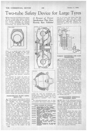
the vehicle, resulting, in extreme cases, in loss of control and perhaps overturning. To prevent this is the object of a special inner tube shown in patent No. 524,990, by the Firestone Tyre and Rubber Co., Ltd., Great West Road, Brentford.
The drawing shows a section of the tyre and tube, the latter comprising the
usual tube fitted with a smaller edition of itself in the interior. Inflation affects both tubes without altering their relative position; but if the outer one bursts, the inner one, being highly elastic, can immediately expand and fill the deflated space. By this means the drop of the vehicle is limited to that due to the difference in pressure only; total deflation cannot occur. The *smaller tube has its own valve, t•-■ permit inflation but prevent undesired , deflation.
• A number of types of valve is described, for example, a ball device, incorporated with the main valve and shown in two forms, devised to constitute no resistance to the entry of air to the inner chamber, but to prevent its escape, whilst being releasable; a similar valve incorporated in the cuter part of the reserve tube and allowing the air to flow outwards slowly, but closing with a sudden rush of air, and finally a flap valve of very simple but reliable design and operating similarly.
PRODUCER-GAS PLANT USING HEAVY OIL
AGAS producer operating on heavy hydrocarbons is described in patent No. 524,881, by Soc. Hellenique Industrielle des Gazofacteurs Athens, Greece. In the illustration the producer, the cooling unit and the gas
carburetter are seen. The engine is started on petrol and some of the exhaust gas is diverted to a nozzle (1) in the producer. Heavy fuel is thereby drawn from a jet (9) whilst air enters through an inlet (3). The resulting mixture is then fired by a sparking plug (2) and proceeds to heat to redness a copper cone (7) and a number of copper balls (6), the whole of which are enclosed in a heat-insulated casing.
When the copper parts become redhot, the air inlet may 'be dosed and the output taken to the engine via the cooler (4) and the air-mixing carburetter (5). By the catalytic action of the incandescent copper, the oil is converted or " cracked " into a true gas.
An expansion-operated pair of electric contacts (8) causes a lamp to light and so to warn the driver that the apparatus is ready for use. The patentee states that the high working temperature, 800-1,000 degrees C., effectively prevents the formation of carbon.
TORQUE CONVERTER FOR PRODUCTION EASY
AN improved hydraulic coupling, ,designed on a production basis, is the subject of patent No. 524.483, from Chrysler Corporation, Michigan, U.S.A. The main parts are intended to be made from steel pressings united by welding.
Referring to the drawing, the outer casing is in two parts, a forward member attached to a crankshaft hub and a rearward part (1) attached by welding around the periphery. The runner is of the usual type, and is mounted upon hub (3) which revolves on a ballbearing centred in the crankshaft boss. The output shaft is splined into the runner hub, projecting through a . spring-closed fluid seal (2).
The vanes are all of sheet metal, spot welded under pressure to their respective elements. A feature of the patent is the use of a step (4) in the otherwise smooth outline of the fluid circuit. This is claimed to give increased slip at very low speeds by interrupting the liquid flow, and thus unwanted " creep " is prevented. It also carries the starter ring (5).
BONDED-RUBBER SPHERICAL UNIVERSAL JOINT
SOME idea of the surprising tenacity of modern rubber-to-metal bonding may be gathered from patent No. 524,954, from M. Julien, Paris. This inventor describes a transmission joint in which both the deflection and the driving torque are resisted solely by the rubber bonding.
The drawing shows the joint itself and the associated flanges of the trans mission system. The joint consists simply of an outer steel shell, a rubber lining, and an inner shell, vulcanized to form a unit. A point of some importance is that the geometric centre of the outer shell is situated slightly to one side of the general centre, whilst that of the inner member is also 'offset,• but in the opposite direction.