


A "MORE THAN ONE PULL" BRAKE.
Page 64
If you've noticed an error in this article please click here to report it so we can fix it.
A Resume of Recently Published Ffatent Specifications.
VETE have on many occasions advocated the employment V V of a brake equipment with which a driver can take a second or third pull should he feel that he hits reached the limit of his movement with his hand lever ; we are glad.
therefore, to see the specification of L. G.. Ward, of LeYtonstone, London, E. No. 276,478, as we know him to be a practical haulier.
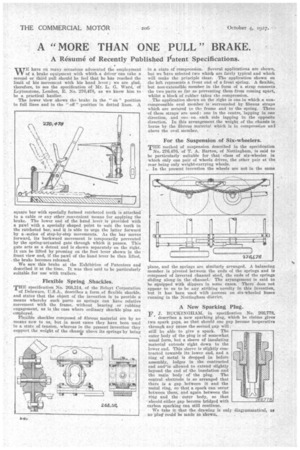
The Tower view shows the brake in the " on" position in full lines and in the " off "•position in dotted lines. A
square bar with specially forthed ratcheted teeth is attached to a cable or any other convenient means for applying the brake. The lower end of the hand lever is Provided with a pawl with a specially shaped point to snit the teeth in the ratcheted bar, and it is able to urge the latter forward by a -series of step-by-step movements. As the bar moves forward, its backward movement is temporarily prevented by the spring-actuated gate through which it passes. This gate acts as a &tent and is shown separately on the right. It can be lifted by pressing on the foot •lever Shown in the front view and, if the pawl of the hand lever be then lifted, the brake becomes released.
We saw this brake at the Exhibition of Patentees and described it at the time. It was then said to be particularly suitable for use with trailers.
Flexible Spring .Shackles. Flexible Spring .Shackles. THE specification No. 268,314, of the Beloyt Corporation -of Delaware, 'U.S.A., describes a form of flexible shackle, and states that the object of the invention is to provide a means whereby such parts as springs can have relative movement with the frame, without bearing or rubbing engagement, as is the case where ordinary shackle pins are employed.
Flexible shackles composed of fibrous material are by no means new to us, but in most cases they have been used in a state of tension, whereas in the present invention they support the weight of the chassis above its springs by being
in a state of compression. Several applications are shown, but we have selected two which are fairly typical and which will make the principle clear. The application shown on the left represents a front end of a front staring. A flexible, but non-extensible, member in the form of a strap connects , the two parts so far as preventing them from coming apart, whilst a block of rubber takes the .compression.
The application shoWn on the right is one in which a noncompressible oval member is Surrounded by fibrous straps which are secured to the frame and to the spring. Three of these straps are used : one in the Centre,"laPping in, one direction, and one on each side lapping in the opposite direction. In this arrangement the weight of the chassis is . borne by the fibrous material which is in compression and • above the oval member.
For the Suspension of Six-wheelers.
THE method of suspension described in the specification
No.276,476, of T. A. Barton, of Nottingham, is said to be particularly suitable for that class of six-wheeler in which only one pair of wheels drives, the other pair at the rear being only weight-carrying wheels.
In the present invention the wheels are not in the same
I lane, and the springs are similarly arranged. A balancing member is pivoted between the ends of the springs and is composed of inverted channel steel, the ends of the springs sliding along in the channel. The arrangement is said to be equipped with slippers in some cases. • There does not appear to us to be any .striking novelty in this invention, brit it has been used with duce is on six-wheeled buses running in the Nottingham -district.
A New Sparking Plug.
F.J. BUCICINGLEAM, in specification No. 266,778, describes a new sparking plug, which he claims gives two spark gaps, so that should one gap become inoperative through any cause the second gap will; still be able to give a spark. The outer body of the ping is of somewhat usual form, but a sleeve of insulating material extends right down to the lower. end. This sleeve is _Slightly contracted towards its lower end, and a ring of .metat is dropped in before assembly, badges in the contracted end and"is allowed to extend slightly .beyond the end of the insulation and the main body of' the plug. The central electrode is so arranged that there is a gap between it and the metal ring, so that a spark can occur between them, and again between the ring and the outer body, so that -should either gap become bridged with carbon sparking can still continue.
We take it that the drawing is only diagrammatical, as no 'pluteould be made'as 'shown,.