


THE FREE WHEEL IN THE TRANSMISSION LINE.
Page 54
Page 55
If you've noticed an error in this article please click here to report it so we can fix it.
A Full Description of the Joseph System, which Employs Two Opposed Free-wheel Clutches Under Control.
IN the article which appeared in The Commercial Motor for September 13th we outlined the principle and object of the introduction of a free wheel in the
transmission line, but in case this article should have escaped the notice of any of our readers we will point out that the object aimed at in the employment of the free wheel is to make gear changing easier by disconnecting the drive transmitted from the forward motion of the vehicle through the propeller shaft to the gearbox, so that when the clutch is withdrawn the gears, not being under the influence of rotary motion derived from either the engine or the propeller shaft. are free to accommodate themselves readily to any change and to mesh easily and without clashing.
The free wheel, being a unidirectional coupling, will allow the engine to drive the rear wheels, but will not permit the rear wheels to drive the engine. It is, however,. fully recognized that it is essential that, when required, the free-wheel action should be suspended and the unidirectional drive converted to a bidirectional drive, thus allowing the engine to be used as a brake, or allowing it to be started by t h e forward movement. of the vehicle when running downhill.
In our article of September" 13th we called attention to the difficulty of transforming a free wheel into a positive drive when the vehicle has gained rapid motion by running down a hill, and the engine either stopped or running very slowly, as the sudden engagement of a positive dog clutch would result in a severe shock.
Being particularly interested in the new departure, namely, the free wheel in the transmission, we have decided to investigate and describe the various efforts which are being made in this direction, and with this object in view we have, first of all, taken the opportunity offered us by Mr. F. A. Joseph to test and make ourselves familiar with his system, which would appear to have many advantages. Other designs and arrangements will he examined and tested by us and, where they merit such treatment, will be dealt with in these pages.
The first point we raised was that mentioned in our article of September 13th and again referred to above, namely, the possibility of shock when turning the free wheel into a positive drive. We find that Mr. Joseph had, like us, fully recognized the importance of this point and had made arrangements whereby it is not possible to convert the free wheel to a positive drive until the engine isrevolvingat a speed that is at least equal to that of the propeller shaft, but not necessarily the same.
DRIVE FROM GEARBOX
To CLUTCH PEDAL
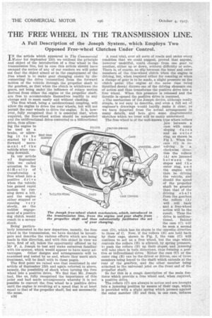
The Joseph free-wheel clutch the transmission line, frees t the propeller shaft and thus of gear c
A road trial, over all sorts of roads and under every condition that we could suggest, proved that anyone, hoWever unskilful, could. change, from one gear to another, either, up or down, without difficulty or noise. There is, of course, no slip'hetween the inner and outer members of the free-wheel clutch when the engine is. driving, but, when required either for coasting or when a change of gear is to be made, a slight pressure on the clutch pedal (the engine at the. same time being throttled down) throws one of the driving elements out of action and thus transforms the positive drive into a free wheel. When this pressure is released and the throttle is opened the positive drive is resumed.
The mechanism of the Joseph device, although really .simple, is not easy to describe, and even a full set of engineer's drawings would hardly make it clear, so we have departed from the actual arrangement in many details, and here give some diagrammatic sketches which we trust will be easily understood.
'The free wheel is of the well-known type where rollers.
jam between a cam with many sloping faces and an outer 66,M5 ring, as shown in Fig 1. When the cam (C) is revolving. in clockwise direction the rollers (A) are jammed between the slopes and the outer ring, and the engine will then be driving the vehicle, and should the speed of the propeller shaft be greater than that of the driving shaf t CAGE CONTROL from the gearbox
the rollers (A) will roll back and a free-wheel action will be the result. Thus the % drive is unidirec tional. Behind the cam (C) will
be seen a second earn (D), which has its slopes in the opposite direction to those of C. Now, if the rollers (B) are held back by their cage, shown in Fig. 2, the cam (C) will continue to act as a free wheel, but the cage which controls the rollers (B) is allowed, by spring pressure, to push the rollers .(B) up their slopes, and jamming will take place in both directions, thus forming a positive or bidirectional drive. Either the cam (0) or the outer ring (E) can be the driver or driven, one of these members being keyed to the shaft which extends at the rear of the gearbox, and the other member being attached to the universal joint on the front end of the propeller shaft.
So far this is a rough description of the main features which provide a free wheel and, when required, a positive drive.
The rollers (C) are always in action and are brought into a jamming position by means of their cage, which is provided with a slight spring which presses against the outer member (E) and thus, in one case, induces
the slight friction necessary to make the cage tend to follow E in whichever direction it may revolve in relation to the cam (C), thus bringing the rollers into a jamming position, or in the other case carries the rollers back and out of contact with E when required. One of the special advantages of this device is that it relieves the rollers from all rubbing contact with E, andthereby prevents flats from wearing on them.
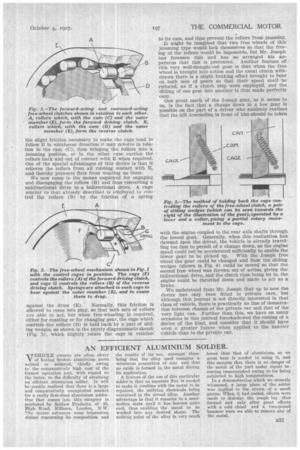
We now come to the means employed for engaging and disengaging the rollers (B) and thus converting a unidirectional drive to a bidirectional drive. A cage similar to that already described is employed to con, trol the rollers (B) by the friction of a spring against the drum (E). Normally, this friction is allowed to come into play, so that both sets of rollers are able to act, but when free-wheeling is required, either for coasting or for changing gear, the cage which controls the rollers (B) is held back by a pair of sliding wedges, as shown in the purely diagrammatic sketch (Fig. 3), which slightly rotate the cage in relation' to its cam, and thus prevent the rollers from jamming.
_It might be imagined that two free wheels of this jamming type would lock themselves so that the freeing of the rollers would be impossible, but Mr. Joseph has foreseen this and has so arranged his apparatus that this is prevented. Another feature of this very well-thought-out gear is that when the free wheel is brought into action and the usual clutch withdrawn there is a slight braking effect brought to bear on both sets of gears so that their speed shall be reduced, as if a clutch stop were employed, and the sliding of one gear into another is thus made perfectly easy.
One great merit of the Joseph gear, so it seems to us, is the fact that a change down to a low gear is possible on the part of a driver who suddenly realizes that the hill descending in front of him should be taken with the engine coupled to the rear axle shafts through the lowest gear. Generally, when this realization has dawned upon the driver, the vehicle is already travelling too fast to permit of a change down, as the engine speed could not be accelerated sufficiently to enable the lower gear to be picked up. With the Joseph free wheel the gear could be changed and then the sliding wedges (shown in Fig. 4) could be moved so that the second free wheel was thrown out of action, giving the bidirectional drive, and the clutch then being let in, the engine could be throttled down and made to act as a brake.
We understand from Mr. Joseph that up to now the device has only been fitted to private ears, but although this journal is not directly interested in that class of vehicle, there is practically no line of demarcation between chassis of the private car and that of the very light van. Further than this, we have on many occasions in this journal foreshadowed the coming of a device of the kind, and consider that it should have even a greater future when applied to the heavier *vehicle than to the private car.