


Simple Design_ of Centrifugal Clutch
Page 56
If you've noticed an error in this article please click here to report it so we can fix it.
A Resume" of Recently Published Patent Specifications Obtainable from the Patent Office, Price is. Each
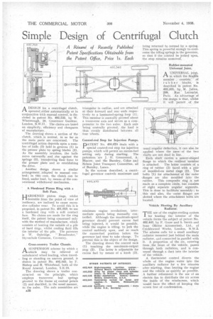
ADESIGN for a centrifugal clutch, operated either automatically or in conjunction With manual control, is disclo•Sed in patent No. 492,532, by W. Whatmough, 29, Grosvenor Gardens, London, N.W.11. The claims are based on simplicity, efficiency and cheapness
of manufacture. . . • The drawing shows a section of the clutch, which is normal, in so far as the main parts are concerned. The centrifugal action depends upon a number of Palls (3) held in grooves (I) in the presser plate by spring blades (2). As the assembly revolves, the balls move outwardly and rise against the springs (2), transferring their force to the Presser plate and so establishing the drive.
. Another design shows a similar arrangement adapted to manual control; in this case, the clutch can be freed, under load, by means of the conventional withdrawal mechanism.
• A Hardened Piston Ring with a • Soft Face.
AR D E NED piston rings, whilst
Idesirable from the point of view of -.resiliency, are inclined to cause excessive cylinder wear. To avoid this it is proposed, in patent No. 491,919, to use a hardened ring with a soft contact face.. No claims are made for the ring itself, the patent being concerned only with the method of manufacture, which consists of beating the outside of a pile of hard rings, whilst cooling fluid fills the ulterior of thc pile. The patentee is W. Oubridge, " Broadwater," Styvecbale Common, Coventry..
Cross-country Trailer Chassis.
ASUSPENSION scheme by which a vehicle may he relieved of unbalanced wheel loading, when travelling or standing on uneven ground, is shown in patent No. 492,342, by F. Bishop and R. Whitehead, both of the Royal Arsenal, London, S.E.18.
The drawing shows a trailer constructed on the principle, which employs transverse leaf springs
• pivoted to the frame ak central points (2) and shackled, in the usual manner, to the axles. The axle assemblies are triangular in outline, and are attached at their forward and rear ends respectively to a laminated-spring loop (1). This member is centrally pivoted about a transverse axis and serves as a compensator to the two axles. Each axle being. centrally pivoted, the load is thus evenly distributed between all four wheels.
Control-rod Stop for Injection Pumps.
PAT ENT No. 490,670 deals with a special control-rod stop for injection pumps, which will permit an excess-fuel setting only during starting. The patentees are J. H. Greenwood, A. Blazow, and the Burnley,. Colne and Nelson Joint Transport Committee, all of Burnley, Lancs.
In the system described, a centrifugal governor controls maximum and minimum engine revolutions, intermediate speeds being manually controlled. Although the maximum-speed governor should prevent excess fuel being injected, it would be possible, while the engine is idling, to jerk the control suddenly open, and so reach the excess-fuel position before the governor had time to take charge. To prevent this is the object of the design.
The drawing shows the control rack (1) touching the maximum-output stop (2). The latter is adjustable for excess fuel by means of a knob (3), being returned to normal by a• spring. This spring is powerful enough to overcome the idling springs in the governor, so that if the control be jerked open, the stop remains unmoved.
Ruhber-mounted Universal Joint.
A UNIVERSAL joint, in which the flexible member consists of rubber blocks, is described in patent No. 492,435, by. M. Julien, 299, Rue LecOurbe, Paris. An advantage of the design is that, whilst it will permit _ of the
usual angular deflection, it can also be applied where the axes • of the two shafts are not dead in line. .
Each shaft carries a saucer-shaped flange to which the resilient member is attached. The latter consists of a ring of rubber (3) faced with a pair of moulded-on metal rings (2). The bolts '(1) for attachment of the outer
flanges are also moulded inLo the
. rubber. This composite ring .is not made as a complete circle, but consists of eight separate angular . segments. This is done to facilitate assembly ; to . this end also, the outer flanges are slotted where the attachment bolts are located.
Vehicle Heating By Auxiliary Radiator.
'THE use of the engine-cooling system 1 for heating the interior of the vehicle forms the subject of patent No. 492,443, by F. Grose and S. Smith and Sons (Motor Accessories), Ltd., of Cricklewood Works, London, N.W.2. The scheme calls for a small auxiliary radiator mounted just behind the main radiator, and connected in parallel with it. A proportion of the air, entering from the front of the vehicle, passes through both radiators, and is conveyed through a duct into the interior of the vehicle.
A thermostat control diverts the whole of the engine water into the auxiliary radiator for a few, minutes after starting, thus heating the engine and the vehicle as quickly as possible. A further refinement is the use of an electric fan to distribute the air across the inside of the windscreen, which would have the effect of keeping the screen free of condensation.