


AN EPICYCLIC GEARBOX.
Page 32
If you've noticed an error in this article please click here to report it so we can fix it.
A R6sumd of Recently Published Specifications.
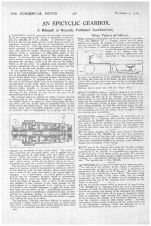
COMPOUND epicyclie gears are the principal components of the change-speed gear which is described in specification No. 221,996, by F. A. Joseph. A planetary cage is keyed to the driving shaft, which, on the drawing which we reproduce herewith from the patent specification, is that which is on the left. This cage carries a number of planetary shafts mounted in ball-bearings located in the ends of the cage, and these are spaced round the central shaft, in the manner which is customary in differential gears of the straight-spur type. Several forms of this novel gear are shown In the one which we illustrate, each of the planetary shafts carries, inside the cage, four spur pinions, ranging in size from the smallest, which is at one end, to the largest, which is at the other. In addition; each planetary shaft projects beyond the driving shaft end of the cage, and has keyed to it, at that end, another spur pinion.
In the specification, this pinion is referred to as being part of the "constraining mechanism." Each of the different sets of planetary pinions engages with corresponding wheels on the driven shaft, which is actually in line with the driving shaft, and supports its spigoted end in a bored hole in the end of the driven shaft, just as is customary in many arrangements of the main shaft of an ordinary gearbox. All the spur wheels on the driven shaft are free to rotate thereon, either directly or through the medium of other sleeves, hollow shafts, or bushes, and provision is made in the way of dog clutches for any one of the gears to be mechatucally locked to the shaft.
The external planetary pinions, to which we have referred as being part of the " constraining mechanism," engage a sun wheel, which is arranged to rotate freely upon the driving shaft, and has, keyed upon its extended boss, a combined clutch and brake drum. The clutch functions in the manner usual with automobile clutches; that is to say, itis normally kept in engagement by a spring, and is dis engaged by movement of the clutch pedal. The brake is also controlled by the clutch pedal, and is applied by the continued motion of that pedal after the clutch is withdrawn. When the clutch is engaged. it couples the sunwheel with which the pinions of the 'constraining mechanism" are in mesh, to the driving shaft ; that is to say, to the planetary cage itself, which is keyed to the driving shaft. The operation of the gear is as follows :—Assume that the gear is in neutral, which is the position in which it is shown in the drawing, with the dog clutches which would connect one or other 'If the main sun-wheels to the driven shaft dis
engaged. As a preliminary, the clutch pedal is also depressed into its "neutral' position, which is intermediate between that in which the clutch is engaged, and that in -which the brake is applied. One or other of the aforesaid dog clutches is then engaged in the usual manner by the manipulation of a change-speed lever working in a gate. The pedal is then further depressed to apply the brake, and thus stop the sun-wheel of the "constraining mechanism" and cause the gear to operate as a transmission gear, by compelling the planetary pinion.s to rotate at a definite rate. The direct drive is obtained by allowing the clutch to engage, this locking the gear as a whole.
The apparatus, although somewhat difficult to explain and possessing a large number of spur pinions, is really little more than a combination of quite simple epicyclic gear units, which can be connected together as is desired.
B48
• Other Patents of Interest.
THE combined lifting jack and brake described in specifica
tion No. 222,019, by J. Gregory, should also be fairly efficient as a sprag. It consists of a long lever, pivoted to the rear axle of the vehicle, and having at its rear end a. shoe, the surface of which is roughened or otherwise formed so as to increase the fictional resistance to ' its passage over the ground when it is pushed into contact with it. The forward end of the lever is coupled up to an operating gear inside the cab. By lifting the front end of the lever, the shoe is brought into contact with the ground, to serve as a brake or a .sprag, whilst continued movement of the gear lifts the axle from the ground altogether.
[Devices which injure the road are FROIsiT-WHEEL braking, which is claimed to be particu larly suitable for heavy vehicles, is described in specification -No. 221,953, by ',J. M. Rubury. The design is an improvement on one which has already been patented, and comprises the arrangement of the brake-shoe-operating came above the steering pivots, in some cases the shafts of the cams being extended, so that the universal joints are displaced relative to the pivotal steering axles. This enables the controlling gear for the brakes to be arranged to clear the steering gear connections.
SUPER-FEED systems for engines of motorcars are a speciality of G. Fornaca, who describes yet another in specification No. 222,037, which refers to a previous construction, and in which the portions of the inlet pipes extending through the crankcase serve to connect and strengthenthe parts of the latter and also to support the compressor for . the system.
IN the shook absorber for Ford ears, which is described in specification No. 222,068, by A. Poe, the connection between the ends of the transverse springs and the frame of the chassis is made through themedium of sliding plates which are compressed together by springs, these tending to dampen the movement of the spring.
EACH arm of the driving star piece of a flexible coupling is connected, according to the design which has been patented by G. W. Hayter, to a diametrically opposite arm on the star piece of the driven shaft, by means of a flexible blade, and all the blades engage a central fulcrum, such, for example, as a bolt passing through the blades from side to side. The specification is No. 221,981.
ACCESSIBILITY to the sleeve valve and its operating gear,
as well as to the cylinder of the engine, is claimedfor the construction-of sleeve-valve gear, which is described in specification No. 221,841, by C. E. Bonner. The sleeve is a rotary one, and is driven by a worm shaft. The worm wheel is cut into the metal of the valve itself, and its overall dimensions are such that the sleeve can be withdrawn upwards, from the top a the cylinder, when the head of the latter is removed.
IN the two-stroke engine which is patented in specification No. 213,398 by F. Laguisse, there are several interesting features, of which the chief is the provision of a slide valve to control the opening and closing of the admission and transfer ports. A-better distribution of the gases is claimed to result, and, in particular, rapid opening and closing of the ports, go as to ensure the passage of a maximum quantity pf gas
into the cylinders, even at high engine speeds. Another interesting feature is the formation of the piston head and of the coinbustion chamber, which are designed so as to increase the turbulence of the gases on compression.