


POINTERS ON PETROL ENGINE VALVES.
Page 31
If you've noticed an error in this article please click here to report it so we can fix it.
Some Useful Tips from Some of Our Driver and Mechanic Readers.
mHE home-made valve-grinding tool
which is described by " E.J.," of Sandbacli, resembles one to which reference was made in these columns a few weeks ago. There are, however, certain important points of difference, notably the use of only one cutting tool instead of two, which make it of sufficient in terest to justify its inclusion here as a novel suggestion meriting the 15s. prize.
The body of the tool is a plain piece of mild steel, of dimensions which may vary slightly in accordance with the size of valve with which the tool is required to deal, but which should in any case be made large enough to accommodate the biggest of such valves. The cutting tool is made from a piece of old fiat file, which must be carefully ground to shape, then sharpened on a grindstone, and finally touched up on an oilstone. The distance-piece is of brass, and should be the same shape as the cutting tool. The edge which comes in contact with the valve should be rounded,so as entirely to eliminate all 'risk of damage to the valve face.
The steel block must be drilled in the centre for the valve stem. If various sizes of valve are used it will be better to drill the block to take a bush, and to keep in stock a set of bushes each of which must be turned on the outside to fit, the hole in the block, and drilled to suit the various diameters of valve stem. The block must be slotted so as to be a good fit for the cutting tool and brass distance-piece. Preferably the inner vertical edge of the slot will be .so arranged that it will serve as a face against which the edge of the cutting tool can be located when it is being set up.
Alternatively, the tool may be set quite clear of this face so that adjustment could be made in every case by setting the edge of the cutter up to the face of the valve. Having set the cutter, the next operation is to set the distance-piece. To do this put a piece of newspaper on the rounded edge, set it up to the valve, secure it in place, and then remove the paper; this Rill afford a clearance of five-thousandths of an inch. The valve is rotated, as shown in the sketch, by means of an ordinary hand-drill.
(-INF of the accompanying sketches shows a valve springlifter which has been designed by " E.W.," of Victoria Park. In his letter he refers to a tool of this kind which was recently described as being suitable for use in connection with a Ford. In that case an S-shaped hook of steel wire was used as a support for the valve-lifting lever. " E. W." prefers a piece of chain to the hook, since its length is adjustable. The chain which is used needs to be about 2 ft. long, and should be of h-in. wire, having links about. 1 in. by in These links can then be opened a little so as to accommodate the 1-in. rcund rod which serves as the actual valve lifter. At one end of the chain a hook is fixed. " E.W." tells uS he used one which he removed from a belt fastener. The method of use is apparent from the sketch, in which the chain is shown 'suspended from a sparking plug.
The lifting lever, which, is has been said, is made from round bar, is splayed and divided at, the end so as to pass the valve stem
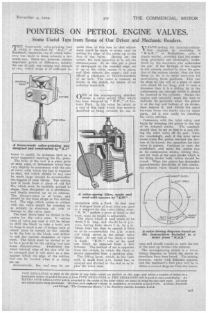
VALVE sefAing for internal-combustion engines is, according to " H.A.B.," of Rotherham, quite a simple matter, provided that the underlying principles are thoroughly understoodby the mechanic ho undertakes the job. If the flywheel of the engine is not already marked to show the position of the various cranks, then the first thing to do is to make provision for ascertaining those positions. This can be done by the aid of a piece of steel wire about 18 in& long, and of such a diameter that it is a sliding fit in the compression tap through which it should be inserted in the cylinder. Rotate the engine and carefully mark the wire to indicate its positions when the piston is at the top and bottom of its stroke, then remove it, and divide the space between those two marks into six equal parts. AU is now ready for checking the valve settings.
Commence with the inlet valve, and begin by bringing the piston to the top
of its exhaust stroke. The camshaft should then be set so that it is just lifting the inlet valve off its seat. Turn the crankshaft, and, if the inlet valve closes when the piston reached the bottom of its travel, the operation for that valve is correct. Continue to turn the crankshaft, and make the piston rise in its compression stroke, during this, and for most of the next stroke which is the firing Stroke, both valves should be closed. When the piston has descended approximately five-sixths of this stroke, the exhaust valve should commence to
open and should remain so until the end of the next up stroke—the exhaust.
The accompanying sketch is a valve. timing diagram on which the above instructions have been based. The setting, however, varies with different engines, and the mechanic's best plan will be to obtain a correct diagram from the maker.