


AN IMPROVED FORM OF GULLY CLEANSER.
Page 21
If you've noticed an error in this article please click here to report it so we can fix it.
Details of the Latest Lacre Machine, which Combines the Open and Closed Circtlit Systems of Gully Emptying.
ONE OF the most successful of the many municipal appliances produced from the works of the Lacre Motor Car Co., Ltd., is their gully emptier. This machine presents the appearance of a partially inverted churn, and, until now, has been made of two types, the open, in which a Vacuum was created in the tank by means of a pump and the sewage, controlled by a suitable valve, sucked into the tank through a large hose, and later came the closed-circuit system, in which the tank is first filled with freshwater, which is forced under fairly high pressure through the dredging jets, ,thus breaking up any solid matter in the gullies. The fluid containing the solid particles is then drawn up the large uptake pipe and transferred into the tank, the sediment is deposited in the tank and the liquid continues to circulate until the gully has been cleansed, the volume of liquid in the gully remaining practically Constant.
In the new cleanser, which ha,s been designed for use in Scandinavia and ordered as the result of the highly Satisfactory work performed by a Lacre machine of the ordinary open gullyemptying type purchased in 1920 for Bergen, these two systems of operation are combined, and it is quite an easy matter to adapt the machine from one to the other.
The chassis employed is the standard 30 h.p. 2-ton Lacre, and the whole design has been simplified so that only one clutch is required for operating the pump. The latter is of a neat but powerful type utilizing four pistons, and it can easily give a pressure of over 20 lb. as well as a high degree of vacuum, but it is provided with a safety valve to prevent too high a pressure being attained. A curious feature of the pump is that it always operates in the same direction and is controlled by a special directional cock.
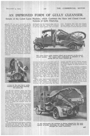
In our illustrations the pump is shown connected up for both the open and closed-circuit systems. In the first case the air is extracted froin the tank and is discharged op the vertical pipe seen at the side of the cab. When it is desired to use the closed system, the connection
between the pump and the lower part of the tank is broken at the pump end, and the end of the connection blocked by attaching it to the plate which can he seen almost. immediately below the connection; a larger hose is also employed between the upper portion of the tank and the upper flange on the casting carrying the cock, the down tube being disconnected for this purpose, whilst the high-pressure water for the jets is obtained from the lower part of the pump.
Many other improvements have been made in the machine. For instance, a winch is now employed for raising or lowering the arm supporting the large hose. Formerly this arm was merely spring loaded, but in the new method the winch itself is driven through a stout
spring, and this gives a certain amount of flexibility to the arm, as the winch may turn slightly in either direction as required.
The gauge which indicates conditions in the tank, of course, is made to register equally efficiently for the two systems.
One of the benefits of being able to use the pump for obtaining comprestion in the tank is that the contents may be discharged to some distance from the vehicle, consequently the vehicle can be used for spraying fields at the sides of the roads, either through its own nozzles, where the distance is not great, or by connecting further lengths of hose where the distances are considerable.