


Patents Completed.
Page 18
If you've noticed an error in this article please click here to report it so we can fix it.
Complete specifications of the following patents will be sent to any address in the United Kingdom upon receipt of eightpence per copy at the Sale Branch, Patent Office, Holborn, W.C.
A ROTARY OIL PUMP.--Albert de Dion and Others.--No. 10,877, 1009, dated, under Convention, 20th November, 19013.—This invention relates to oil pumps of the rotary gear type. According to this invention the body or casing of the pump is made integral with the bearing of the crankshaft. The underside of the crankshaft bearing is extended and suitably bored to receive the pump gear wheels, And a plate is bolted to the extension so as completely to enclose the gear wheels. The spindle of one of these gear wheels is extended beyond the CaS ing and carries another gear wheel which gears with a pinion that is fast on the crankshaft. The suction pipe is situated at the bottom of the crank casing, and the pump delivers through an annular passage in the crankshaft bearing to a vertical conduit situated immediately above. The bearing for an intermediate pinion is made hollow and communicates with the vertical conduit before mentioned. Within this hollow spindle, a
spring relief valve is arranged, which, on excessive pressure being produced by the pump, allows the excess of oil to return ' to the crank casing.
SPLASH-GUARD.— Akatyeff.— No. 20,495, dated 29th September, 1908.— This invention relates to a device for preventing side splashing from the wheels of motor vehicles. It comprises a number of chains depending from a holder which is attached to the axle by niedns of a ring and set screw. The device is vertically 'adjustable so that it may be applied to any vehicle.
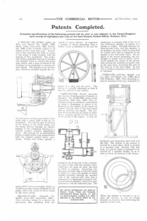
CARBURETTER.— Societe A110!Vine des Anciens Etablissements Panhard et Levassor.—No. 12,043/1909, dated, under Convention, 29th July, 1908.—This invention relates to automatic carburetters in which a diaphrag-rn or piston is influenced by the suction of the engine to control both the area of the fuel nuzzle and an auxiliary air supply. The preSent invention has for its object to maintain a constant portion of fuel and air, at all speeds of the engine. A tube ar ranged at the lower end of the carbureter, and in line with the throttle valve, constitutes the main air inlet, the area of which is constant. Projecting into his main-air-inlet tube is the fuel nozzle n which is a valve, the spindle of which extends upwardly through the opposite wall of the main-air-inlet tube and is connected to a diaphragm arranged within a cylindrical chamber, which is in communication with the induction pipe. The
diaphragm is normally held at the top of the cylindrical chamber by means of a spring or weight. Situated between the main-air-inlet tube, and this chamber is an auxiliary-air inlet, which is controlled by a slide valve that is connected to the spindle of the fuel-nozzle valve. On the speed of the engine increasing, the diaphragm or piston will be drawn downwards against the action of the spring, thus opening the auxiliary-air ports, and, at the same time, increasing the area of the opening in the fuel nozzle. In this way a constant proportion of air and fuel is obtained.
FURNACES.—Fletcher Russell and Co., Ltd., and Others.—No. 4,864, dated 27th February, 1909.—This invention relates to furnaces of the type employed for hardening and tempering steel tools and the like. The bottom of the furnace is carried by a steel plate which is pivoted to a movable rack. Gearing with this rack, is a pinion which is arranged to be rotated by . a suitable handle, so as to raise or lower the bottom of the furnace.
When the bottom is lowered so as to clear the furnace, it may he swung laterally on its pivot, thus facilitating the removal of hot tools.