


NEW DAIMLER FLAT-ENGEN
Page 50
Page 51
Page 52
If you've noticed an error in this article please click here to report it so we can fix it.
Centrally Mounted Power Unit Provides Straight-through Transmission Line. Steering Layout Allows Full Wheel Deflection. Radiator and Fan Located to Rear of the Front Axle
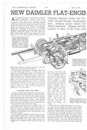
AN outstanding feature of the Daimler underfloorengined single-decker chassis is that bodies with front, centre or rear entrance can be mounted on i, with equal facility. The frame members are flat and parallel with the ground from the front end to the centre line of the rear axle, and all projections above the frame have been avoided The standard chassis has a wheelbase of 16 ft. 4 ins., and whilst designed to accommodate 8-ft.-wide bodies, minor hubassembly modifications enable a 7-ft. 6-in, body to be fitted. The overseas version of the chassis has a wheelbase of 17 ft. 6 ins and is suitable for 32-ft. bodies of
either width. Both are available with rightor left-hand steering and are known as the Freeline.
The prototype is powered by a Gardner 6HLW 8.4litre unit developing 112 b.h.p. at 1,700 r.p.m., this engine being interchangeable with a new Daimler flat engine based on the CD650 10.6-litre unit. This has a rating of 125 b.h.p. at a governed speed of 1,650 r.p.m., and is available with a higher rating of 134 b.h.p. at 2,000 r.p.m. Road speeds in the direct-drive top gear with the standard back-axle ratio of 4g to 1 and the wheels fitted with 9.00 by 20-in. tyres, are 42,2 m.p.h. at 1,700 r.p.m., 44.4 m.p.h. at 1,800 r.p.m, and 49.2 m.p.h at 2,000 r.p.m, This tyre size is used on the vehicles with 7-ft. 6-in, bodies.
Crankshaft Centre Line Offset
In both cases the engine is flexibly mounted for singleaxis oscillation about the principal axis, and the positioning of the unit is such that the only changes required when substituting one type for the other are confined to the support brackets and controls. The crankshaft centre line in each instance is located to the nearside, and provides an approximately neutral transmission line with the gearbox and offset worm drive.
Prolonged operational tests of a standard unit running at 2,000 r.p.m. proved that the higher output of 134 b.h.p. could be sustained without sacrificing reliability or reducing the period between overhauls. The maximum governed speed is still well below that of the sixth order critical.
The new Daimler CD650H underfloor engine is based on the CD650 vertical unit. It has a well-baffled lightalloy 6-gallon sump of the conventional " flat " shape. reversed connecting rods to give upward splash. and cooling-circuit arrangement with outlets at the top and c12 an inlet on the lower side. The water pump is mounted on the underside and is driven by vee belts from the end of the crankshaft. Other features include a larger intake manifold with singlepipe branches, a timing-case breather connected to the induction manifold, and a reshaped exhaust manifold. Minor changes to the camshaft lubrication system have been made, and the relief valve of the main lubrication system now discharges direct into the sump. Apart from extensions on both sides for mounting purposes, the timing case remains unaltered.
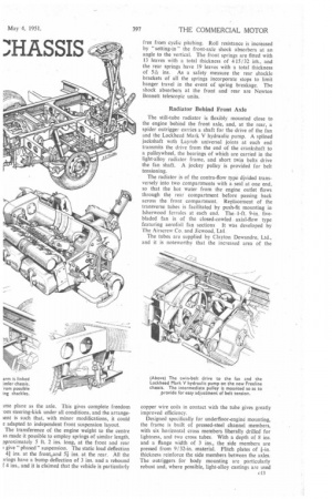
Chassis features of outstanding interest are found in the layout of the steering, the details of the flexible suspension and the arrangement of the cooling system. Maximum manoeuvrability is achieved by the use of a central pivot, which obviates obstruction of the wheels by the drag link, and enables the lock to be increased to the limit imposed by the springs. The upper arm of the pivot is linked to the drop arm of the steering box and the lower pivot-arm to the steering arm of the offside hub assembly. The lower arm is horizontal and moves about the pivot connection in approximately the
ime plane as the axle. This gives complete freedom .om steering-kick under all conditions, and the arrangelent is such that, with minor modifications, it could e adapted to independent front suspension layout. The transference of the engine weight to the centre as made it possible to employ springs of similar length, pproximately 5 ft. 2 ins, long, at the front and rear give "phased" suspension. The static load deflection 41 ins, at the front.and n ins, at the rear. All the nings have a bump deflection of 3 ins, and a rebound 4 ins., and it is claimed that the vehicle is particularly free from cyclic pitching. Roll resistance is increased by "setting-in" the front-axle shock absorbers at an angle to the vertical. The front springs are fitted with 13 leaves with a total thickness of 415132 ids., and the rear springs have 19 leaves with a total thickness of 54 ins. As a safety measure the rear shackle brackets of all the springs incorporate stops to limit hanger travel in the event of spring breakage. The shock absorbers at the front and rear are Newton Bennett telescopic units.
Radiator Behind Front Axle
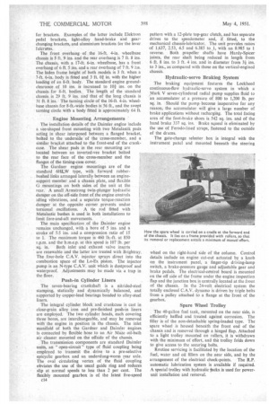
The still-tube radiator is flexibly mounted close to the engine behind the front axle, and, at the rear, a spider outrigger carries a shaft for the drive of the fan and the Lockheed Mark V hydraulic pump. A splined jackshaft with Layrub universal joints at each end transmits the drive from the end of the crankshaft to a pulieywheel, the bearings of which are carried in the light-alloy radiator frame, and short twin belts drive the fan shaft. A jockey pulley is provided for belt tensioning.
The radiator is of the contra-flow type divided transversely into two compartments with a seal at one end, so that the hot water from the engine outlet flows through the rear compartment before passing back across the front compartment. Replacement of the transverse tubes is facilitated by push-fit mounting in Isherwood ferrules at each end. The 1-ft. 9-in, fivebladed fan is of the closed-cowled axial-flow type featuring aerofoil fan sections It was developed by The Airscrew Co. and Jicwood, Ltd.
The tubes are supplied by Clayton Dewandre, Ltd., and it is noteworthy that the increased area of the copper wire coils in contact with the tube gives greatly improved efficiency.
Designed specifically for underfloor-engine mounting, the frame is built of pressed-steel channel members, with six horizontal cross members liberally drilled' for lightness, and two cross tubes. With a depth of 8 ins. and a flange width of 3 ins., the side members are pressed from 9/32-in. material. Flitch plates of i-in. thickness reinforce the side members between the axles. The outriggers for body mounting are particularly robust and, where possible, light-alloy castings are used for brackets. Examples of the latter include Elektron pedal brackets, light-alloy hand-brake and gearchanging brackets, and aluminium brackets for the lever fulcrums.
The front overhang of the 16-ft. 4-in, wheelbase chassis is 5 ft. 9 ins, and the rear overhang is 7 ft. 8 ins. The chassis, with a 17-ft. 6-in, wheelbase, has a front overhang of 6 ft. 5 ins, and a rear overhang of 7 ft. 9 ins. The laden frame height of both models is 3 ft. when a 7-ft. 6-in, body is fitted and 3 ft. Of in. with the higher loading of an 8-ft. body. The standard engine groundclearance of 10 ins, is increased to 101 ins, on the chassis for 8-ft. bodies. The length of the standard chassis is 29 ft. 9 ins, and that of the long chassis is 31 ft. 8 ins. The turning circle of the 16-ft. 4-in, wheelbase chassis for 8-ft.-wide bodies is 56 ft., and the swept turning circle with a body fitted is approximately 64 ft.
Engine Mounting Arrangements
The installation details of the Daimler engine include a vet-shaped front mounting with two Metalastik pads acting in shear interposed between a flanged bracket, bolted to the underside of the cross-member, and a similar bracket attached to the front-end of the crankcase. The shear pads in the rear mounting are located between an inverted-vee bracket bolted to the rear face of the cross-member and the flanges of the timing-case cover.
The Gardner engine mountings are of the standard 61-ILW type, with forward rubberbushed links arranged laterally between an enginesupport member and a chassis plate, and flexible 0 mountings on both sides of the unit at the rear. A small Armstrong twin-plunger hydraulic damper on the off-side front of the engine controls idling vibrations, and a separate torque-reaction damper at the opposite corner prevents undue torsional oscillations. A tie rod fitted with Metalastic bushes is used in both installations to limit fore-and-aft movements.
The main specification of the Daimler engine remains unchanged, with a bore of 5 ins, and a stroke of 5:5 ins, and a compression ratio of 15 to I. The maximum torque is 460 lb.-ft. at 850 r.p.m. and the b.m.e.p. at this speed is 107 lb. per sq. in. Both inlet and exhaust valve inserts are renewable and the latter are treated with Brightray. The four-hole C.A.V. injector sprays direct into the combustion space of the Lo-Ex piston. The injector pump is an N-type C.A.V. unit which is dustproof and waterproof. Adjustments may be made via a trap in the floor.
Push-in Cylinder Liners
The seven-bearing crankshaft is a nitrided-steel stamping, statically and dynamically balanced, and supported by copper-lead bearings bonded to alloy-steel liners.
The integral cylinder block and crankcase is cast in close-grain alloy iron and pre-finished push-in liners are employed. The two cylinder heads, each covering three bores, are interchangeable, and may be removed with the engine in position in the chassis. The inlet manifold of both the Gardner and Daintier engines is connected by flexible hose to an Air Mize oil-bath air cleaner mounted on the offside of the chassis.
The transmission components are standard Daimler units, an " open-circuit" type of fluid coupling being employed to transmit the drive to a pre-selective epicyclic gearbox and an underslung-worm rear axle. The oval circulating vortex of the fluid coupling obviates the use of the usual guide ring and reduces slip at normal speeds to less than 2 per cent. The flexibly mounted gearbox is of the latest five-speed
c14
pattern with a 12-plate top-gear clutch, and has separate drives to the speedometer and, if fitted, to the mechanical chassis-lubricator. The unit provides ratios of 1.637, 2.53, 4.5 and 6.385 to _1, with an 8.985 to 1 reverse. Both propeller shafts have Hardy-Spicer joints, the rear shaft being reduced in length from 6 ft. 8 ins. to 3 ft. 4 ins, and in diameter from 31 ins. to 3 ins., as compared with those on the vertical-engined chassis.
Hydraulic-servo Braking System
The braking equipment features the Lockheed continuous-flow hydraulic-servo system in which a Mark V seven-cylindered radial pump supplies fluid to an accumulator at a pressure of 800 to 1,200 lb. per sq. in. Should the pump become inoperative for any reason; the accumulator will give a large number of brake applications without recharging. The total facing area of the foot-brake shoes is 542 sq. ins, and of the hand brake 337 sq. ins. Brake squeal is eliminated by the use of Ferodo-lined straps, fastened to the outside of the drums.
The gate-change selector box is integral with the instrument panel and mounted beneath the steering wheel on the right-hand side of the column. Control details include an engine cut-out actuated by a knob on the instrument panel, a finger-tip driving-lamp switch, a brake-pressure gauge and adjustable gear and brake pedals. The electrical-control board is mounted on the off side of the frame under the engine inspection flap and the junction box is centrally located at the front of the chassis. In the 24-volt electrical system the totally enclosed C.A.V. dynamo is driven by triple belts from a pulley attached to a flange at the front of the gearbox.
Spare Wheel Trolley
The 40-gallon fuel tank, mounted on the near side, is efficiently baffled and treated against corrosion. The filler is of the non-detachable spring-loaded type. The spare wheel is housed beneath the front end of the chassis and is removed through a hinged flap. Attached to a light trolley mounted on rollers, it is withdrawn with the minimum of effort, and the trolley folds down to give access to the securing bolts.
Routine servicing is facilitated by the location of the fuel, water and oil fillers on the near side, and by the arrangement of the electrical check-points. The R.P. automatic lubrication system is available if required. A special trolley with hydraulic -lacks is used for powerunit installation and removal.