Unusual Layout for Independent Suspension
Page 40

If you've noticed an error in this article please click here to report it so we can fix it.
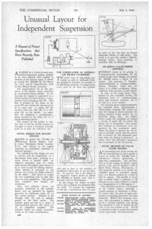
ASCHEME for a rubber-bushed independent suspension system, claimed to be more dnrable when applied to vehicles of the heavier types, is shown in patent No, 518,597 by the Rover Co. , Ltd., and P. Scott-Iversen, both of New Meteor Works, Coventry.
The iniprovements lie in the geometry of the scheme, many variations in construction being possible. In the drawing the chassis is suspended on a helical spring (1) held between a crossmember and a swinging link (6). This link is pivoted on the frame at the point •(7) and, carries the steering pivot at its outer end. A radius rod (3) extends from the link (6) to a balljoint (2) on the chassis. An upper link (4) completes a parallelogram, being pivoted at the point (5) to a shock-absorbing device.
The essence of the patent is that the axes of all the pivotal points are arranged to have a common meetingpoint at or near the hall-joint (2).
NOVEL DESIGN FOR ROTARY ENGINE
SHOWN in patent No. 517,881 by Wilkerson Rotary Engine, Ltd., 8, Great Winchester Street, London, E.C.2, and others, is an engine requiring no crankshaft, camshaft or internal gearing.
The cylinders in this design are two in number and lie tangentially on a disc-shaped back plate, rotating as a whole about a central shaft. An elliptical stationary cam (1) causes roller-ended bell-cranks (part shown at 3) to rock to and fro during rotation, which motion is conveyed to the pistons via a lever (4) freely mounted on the shaft. This serves to couple the two connecting rods so that they move in exact opposition. The pistons thus complete four strokes per revolution.
Inlet and exhaust valves are normally positioned in the cylinder heads, and are operated by tappets governed by stationary cams (2) on the central portion. Mixture is fed through tube (5) and is suitably ported to the inlet valves. The exhaust gases are led to a series of interconnected grooves (8) which act as an expansion chamber. The cylinder heads are easily accessible, being on the outer circumference. FOR LUBRICATION OF HYDRAULIC BRAKE CYLINDERS
TIIE usual type of expanding cupwasher as used in hydraulic braking systemS. is inclined, on account of its self-fitting property, to scrape away every trace of oil from the cylinder
wall and so lead to the paradox of insufficient lubrication in an oil cylinder. To prevent this is the object of an improved washer shown in patent No. 518,600 by Bendix, Ltd., and G. Roberts, both of Birmingham.
In this design the washer is made with a rim of slightly less diameter than the body. To prevent the expansion of the rim, a moulded-in wire (1) may
be used, or the rim may be formed somewhat thicker at this point. The result is to give the washer a Michellbearing action, thus, ensuring an unbroken film of lubricant.
OIL-SERVO VALVE-TIMING CONTROL INTEREST seems to be arising in 1 advance-retard mechanisms for the control of the valve timing, and patent No. 518,581 shows a device of this nature. The patentee, F, Porsche, Spitalwaldstrasse 2, Stuttgart-Zuffelfhausen, Germany, states that the object is to obtain satisfactory idling, combined with economy at full output.
In view of the large loads transmitted by the camshaft system, the adjusting force is correspondingly . great, and recourse, therefore, has to ' be had to a servo system.
The drawing shows diagrammatically the camshaft drive, incorporating a helical-spline coupling (6), which can alter the timing in known manner, the sliding member being moved by an hydraulic piston (5). An engine-' driven pump (2) circulates oil around a circuit of pipes (4) to which the piston (5) is connected. The circuit also cdntains an obstructor valve (I) operated by the accelerator pedal. When the latter is moved, the oil circuit is partially closed and the piston (5) is moved by the increased pressure, thtls the timing is advanced. A safety valve (3) prevents a dangerous rise of pressure in the oil system.
NOVEL METHOD OF VALVE GUIDE MAKING
AN interesting and novel scheme for the manufacture of valve_ guides is shown in patent No. 518,284 from a well-known concern specializing in high-class components. The specification is in the names of Hardy, Spicer and Co., Ltd., and W. Sparrow, both of Birch Road, Witton, Birmingham, 6. The proposed method is to mould the complete guide in powdered sponge iron, of a fineness passed by a mesh of 0.01 in. square. The powder is forced into a mould under a pressure of 25 tons per sq. in., after which it is heated to a temperature of 1,100 degrees C.
This operation produces a component of the correct outline, although a certain amount of distortion is likely. To correct this, the piece is again subjected to a pressing operation, this time unheated. Before final pressing, however, the valve-guide is soaked in hot oil in a vacuum chamber, and during this operation is said to absorb 30 per cent, of its own volume of oil. The oil so retained is said to render the finished article practically. self-lubricating.•


