


Patents Completed.
Page 20
If you've noticed an error in this article please click here to report it so we can fix it.
Complete specifications of the following patents will be sent to any address in the United Kingdom upon receipt of eightpence per copy at the Sale Branch, Patent Office, Holborn, W.C.
CONTROL AND CALL APPARATUS FOR CAB RANKS.—Orcs1.—No. 26,707, dated 17th November, 1910.— LI this spee:flcation there is described and illus trated a mitt-oiling apparatus fee a cab
traffic system. By obtaining cumplete information as to the state of the va,rieus cab ranks and the demands on them, and by putting the control of a number of ranks in the hands of a single superintendent, a more-efficient and economical service of cabs call be obtained. There is also described means for keeping a record of the demand for the utilization of each cab rank, so that the oceupatien can be adapted to the average demand. On each rank under control there is preriled the apparatus shown in the bottom left-hand corner of the diagram. Each driver on arriving at the rank inserts in this apparatus a check which he carries with him ; the insertion of one of these checks sends an indication to the central station that the cab is on the rank. When all the cheeks have been removed another signal is sent showing that the rank is empty. There is also provided an indicator to direct drivers of superfluous cabs from one rank to go to a neighbouring rank which is empty or where there is a greeter demand. 'There is also provided a special means for calling up the superintendent reminding him that no cabs are available there. If necessary, arrangements can be included for putting the registering apparatus out of circuit at night, so that a superintendent is only required during the day. There is also described means whereby for night service a coin-operated mechanism can be used for calling cabs from neighimurin,g ranks.
TWO-CYCLE ENGINE.—Kemp.—No. 21,500, dated 15th September, 1.910.—In accordance with the invention described in this specification, an annular pump piston is provided surrounding the working piston ; by means of this the scavenging charge is delivered from the under side of the pump piston and the mixtme from the other side successively to the working cylinder. This pump piston is preferably formed integral with a eleeve in the cylinder in which the working piston operates. The timing and delivery of the scavenging charge and of the mixture are controlled by ports in the
sleeve and in the working piston. The mixture is delivered during the upstroke of the working piston, so that for a short
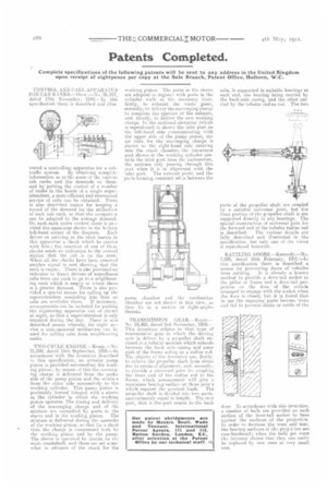
6 time the charge is compressed both by the working piston and by the pump. The sleeve is operated by cranks on the main crankshaft, and these nice set somewhat in advance of the crank for the working piston. The ports in the sleeve are adapted to register with ports in the cylinder walls at the necessary time, firstly, to exhaust the waste gases, secondly, to deliver the scavenging charge to complete the ejection of the exhaust, and, thirdly, to deliver the new working charge. In the stectional elevation (which is reproduced) is shown the inlot port an the left-hand side eoznmunicating with the upper side of the pump piston, the air inlet for the scavenging charge is shown on the right-hand side entering into the crank chamber, the transverse port shown in the working cylinder controls the inlet pert from the carburetter, the mixture only pa-acing through this port when it is in alignment with the
inlet port. The exhaust ports, and the ports forming communi atien between the pump chamber and the combustion chamber are not shown in this view, as they lie in a ses-tion at right-angles thereto.
TRANSMISSION -GEAR.-Royce.— No 25,485, dated 2nd November, 1910.— This invention rekites to that type of transmissiongear in which the driving axle is driven by a propeller shaft enclosed in a tubu'ar member which extends between the back axle casing and some part of the frame acting as a radius rod. The objects of the invention are, firstly, to relieve the propeller shaft from stress due to errors of alignment, and. secondly, to provide a universal joint for coupling the front odd of the radius rod to the frame, which arrangement will give a maximum hearing surface at these poires which support the greatest loads. The propeller shaft is divided into two parts. approximately equal in lengthThe relr part, that is the part nearer to the back axle, is supported in suitable bearings at each end, one bearing being carried by the hack-axle casing, and the other carried by the tubular radius rod. The two parts of the propeller shaft are coupled by a suitable universal joint, but the front portion of the propeller shaft is not supported directly in any bearings. The special construction of universal joint for the forward end of the tubular radius rod
is described. The various details are fully described and illustrated in the specification, but only one of the views is reproduced herewith.
RATTLING DOORS.—Kennedy.--No. 3,930, dated 16th February, 1911.-In this specification there is described a means for preventing doors of vehicles
from rattling. It is already a known method to provide a dove-tail socket in the pillar or frame and a dove-tail projeetien on the door of the vehicle arranged to engage with the socket when the door is closed, hut it is found that in use the engaging parts become worn and fail to prevent shake or rattle of the door. In accordance with this invention, a number of belle are provided on each surface of the dove-tail socket to bear against the surfaces of the projection. In order to decrease the wear and tear, the bearing surfaces of the projec:ion are ease-hardened; when the balls get worn the inventor claims that they can easily be replaced by new ones at very small cost.