


A Four-wheel-drive Layout
Page 76
If you've noticed an error in this article please click here to report it so we can fix it.
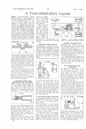
AANY four-wheel-driven vehicles IVIhave means for disconnecting the front drive while on good roads, so as to avoid unnecessary wear. If, however, the vehicle should get into difficulty on soft ground it must be brought to a standstill before the front drive can be engaged. This means that the forward momentum is lost at the moment when it would be most helpful.
Patent No. 722,269 (The TimkenDetroit Axle Co., Detroit, Michigan, U.S.A.) discloses an automatic driving arrangement in which the front wheels are driven only when the rear ones slip. The full tractive effort is therefore available at any moment, but is not in actual use unless circumstances warrant.
The action is obtained by incorporating a simple freewheel in the front transmission and driving the rear axle about 8 per cent. slower. This means that if the rear wheels are fully tractive, the front transmission overruns. But if rear slip occurs, all the wheels come into action, the rear ones then driving with 8 per cent. slip.
In the drawing, the shaft (1) to the front is made to run faster than the rear shaft owing to the differing size of the two gears (2 and 3). The freewheel is shown in the front drive at 4. The freewheel is of the reversible type, so that the same action can be obtained in either direction of running.
A GRINDING WHEEL FOR INJECTION-PUMP CYLINDERS
THE standard peripheral speed for emery wheels is about 5,000 ft. per min.; whilst this is easily reached on large wheels, for small ones used internally a very high rotational speed is called for. For example, to grind
the bore of an injection-pump cylinder, the wheel has to be about 0.2 in. diameter, and to reach the standard speed such a small wheel must be run at something like 120,000 r.p.m. At speeds of this order concentricity is vital, otherwise the wheel will bend its spindle and fly off.
Patent No. 722,354 shows a wheel intended for these small bores, the patentee being M. Copper, Piazza A34 Carrara 15, Milan, Italy. In the scheme shown, the wheel and its spindle are made in one piece by moulding.
When the mould is being filled, a charge of abrasive grains is introduced into one end, the rest being plastic material. The result is a moulding, one end of which is an emery wheel, as indicated at 1. The taper bore (2) is made to fit the spindle of the grinding machine.
INJECTOR NOZZLE DESIGN A CCORDING to Sulzer Freres S.A., Winterthur, Switzerland, a problem which is often encountered in fuel injectors is the formation of deposits in and around the nozzle. The remedy is said to be a matter of relative proportions, and the patent No. 720.916, proceeds to describe a favourable design.
The drawing shows an enlarged view of a nozzle tip with the pintle valve in position. The chief points of the patent are: The fuel space (1) Should be equal to 0.4 of the volume of the whole cone with the pintle valve absent; the distance between the cooling space (2) and the spray jet (3) should not be larger than the maximum diameter of the valve seating and, finally, the spray jets should not be longer than four times their diameter.
A PUMP FOR PETROL INJECTION A PETROL-INJECTING pump is 1-1clealt with in patent No. 722,388 (P. Vanni, 17 Via la Beatrice &Este, Milan, Italy).
In the drawing, I is the plunger which operates on the usual principle for varying the output. The rotary setting is made by a rack-and-pinion connection with a flexible diaphragm (2) subject to intake suction.
The actuating cam is novel, being of snail form. It makes the plunger descend slowly and then, as block 3 snaps over the sharp edge of the cam, it suddenly applies the full force of the
spring (4). The injection stroke has therefore a short constant duration which is the same for all engine speeds.
MAKING GUDGEON PINS
PATENT No. 722,686 (The Ohio Crankshaft Corp., Cleveland/ Ohio, U.S.A.) gives particulars of a new method of making gudgeon pins. A bar of steel, in its annealed state, is nicked at intervals with a parting tool, the distance between the nicks being the required length of pin.
By induction-heating methods, the outer surface only is then hardened and tempered. The next operation is to drill out the soft centre, during which the pins break off when the drill reaches the nicks.
AN AUTOMATIC BRAKE ADJUSTER •
ARATCHET-OPERATED brake adjuster fo• use with a servomotor is shown in patent No. 721,133 (Ford Motor Co. Ltd., 88 Regent Street, London, W.1). The scheme is said to be suitable for use with an automatic transmission system employing a contracting-band brake, but no details of this are given.
Referring to the drawing, a servocylinder (1), when• operating, thrusts on a screwed rod (2) which carries a nut member (3); this is the actuating unit of the brake mechanism. Between the end of the screwed rod and stop-face (4) is a ratchet-and-pawl mechanism (5).
This is worked by endwise compression, but the sliding motion is transformed into rotary motion by a pair of helical slots containing pins (6). When sufficient slack has accumulated the pawl moves over one tooth on the ratchet and turns the screwed rod slightly. This has the effect of shifting the brake actuating nut along the screw to set up a Mk Zero position.