


A Coil-magneto Ignition System Recently Published
Page 52
If you've noticed an error in this article please click here to report it so we can fix it.
Patent Patent Specifications
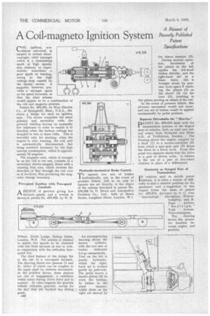
rOIL ignition. now ‘....,almost universal, is subject to certain disadvantages, chief amongst which is a diminishing spark at high speeds, and, contrary to expectations, sometimes a poor spark at starting, owing to the high voltage drop caused by the starter motor. A magneto, however, provides a stronger spark as the speed increases, so that the ideal scheme would appear to be a combination of the coil and magneto systems.
Patent No. 478,351, by Wico Electric Co., of Springfield, Mass., U.S.A., discloses a design for such an ignition unit. The device comprises the usual primary and secondary coils, the primary winding having an unusually low resistance in order to enable it to function when the battery voltage has dropped to two or three volts. This is intended only for starting ; when the engine is once running, the coil unit is automatically disconnected, this being rendered necessary by the high current consumption, which is approximately 12 amperes.
The magneto unit, which is brought in as the coil is cut out, consists of a stationary electro-magnet, fitted with a rotating iron core, which reverses the direction of flux through the coil core as it revolyeS, thus producing the magnetic change necessary.
Five-speed Gearbox with Two-speed Layshaft.
ADESIGN of gearbox giving five forward speeds and a reverse is shown in patent No. 478,585, by W. B.
Wilson, North Lodge, 'Paling Green, London, W.5. The scheme is claimed to enable five speeds to be obtained with but little increase of size or cost, in comparison with the orthodox fourspeed box.
The chief feature of the design lies in the • use of a two-speed layshaft. The drawing shows two pinions (1 and 2), either of which can be coupled to the input shaft by endwise movement. In the position shown, these pinions are . out of engagemelit, A condition which exists during direct drive and in neutral. • In other respects the gearbox folloWs orthodox practice, except for the fact that the layshaft has sliding gears.
B42 Hydraulic-mechanical Brake Control.
TO operate two sets of brakes hydraulically, yet, in the event of pressure failure, still to be able to operate one set directly, is the object of the scheme described in patent No. 478,328 by D. Brock and Automotive Products Co., Ltd., both of Brock House, Laugh= Street, London, W.I.
An accompanying drawing shows the master cylinder, with the two sets of brakes indicated d jag r ammatically. That on the left is purely hydraulic, whilst the righthand set is worked partly by pull-rods. The pedal moves a master piston (4) to work the hydraulic brakes in the usual manner, whilst those on the right are moved by the sleeve member (2).
During normal operation, movement of the piston to the left applies the left-hand brakes directly, and the right-hand set at a lesser force; this is brought about by pressure from space 5 reaching the piston (1) on the sleeve (2) via the bore (3), resulting in this piston moving on ahead of the rest.
In the event of pressure failure, this advance movement would not occur, and one set of brakes would be applied mechanically by pedal pressure.
Separate Driveshafts for "Heavies."
PATENT No. 476,619 deals with the transmission systems of the largest sizes of vehicles, both on road and rail, and comes from Nydqvist and Holm
A.B., of Trollhattan, Sweden. The drawing shows the engine, coupled by a shaft (1) to a torque-converter (2) from which a spur-gear pair (3) drops the drive to a lower level. From this point two separate shafts take the drive to a pair of driven axles. A feature is the use of a pair of free-wheel clutches in place of a differential.
Generator as Integral Part of Transmission.
I N vehicles used as mobile power stations, it is often a matter of difficulty to find a suitable position for the generator, and a suggestion in this respect forms the basis of patent No. 478,614, disclosed by S. G. Guy, " Sauchieleigh " Albrigh ton, Wolverhampton, and R. Dean Averns, "Rayleigh," York Avenue, Wolverhampton.
The drawing shows the generator location between_ engine and gearbox.