


A NEW IDEA IN TRAILERS.
Page 30
If you've noticed an error in this article please click here to report it so we can fix it.
A Resume of Recently Published Patents.
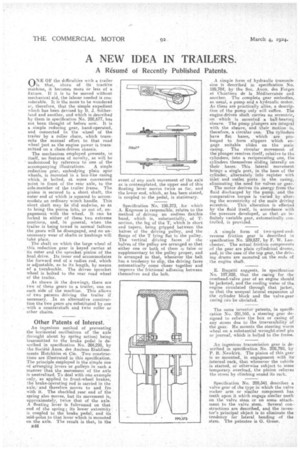
el NE Oh' the difficulties with a trailer klis that, shorn of its tractive Machine, it becomes more or less of a fixture. If it is to he moved without mechanical aid, the labour needed is considerable. It is the more to be wondered at, therefore, that the simple expedient which has been devised by B. J. Sather
land and another. and which is described by them in specification No, 208,677, has not been thought of before now. It is a simple reducing gear, hand-operated, and connected to the wheel of the trailer by a roller chain, which transmits the -manual effort to that road wheel just as the engine power is transmitted on a chain-driven chassis,
The mechanism employed presents, in itself, no features of novelty, as will be understood by reference to one of the accompanying illustrations. A single redaction gear, embodying plain spar wheels, is mounted in a box-like casing which, is bolted, at some convenient Point in front of the rear axle, to the side-member of the trailer frame. The pinion is secured to a short shaft, the outer end of which is squared to accommodate an ordinary winch handle. This short shaft may be slid endwise, so as to bring the pinion into, or out of, engagement with the wheel. It can be locked in either of these two extreme positions, and, in general, when the trailer. .is being towed in normal faShion the gears will be disengaged, and no unnecessary wear of shafts or bushings will take place.
The shaft on which the large wheel of this', reduction gear is keyed carries at its outer end the sprocket, pinion of the final drive. Its inner end accommodates the forward end of a radius rod, which is adjustable, as to its length, by /neaps of a turnbuckle. The driven sprocket wheel is bolted to the rear road wheel of the trailer.
As shown a the drawings, there are two of the :se gears to a trailer, one on each side of the machine. This allows of two persons driving the trailer if necessary. In an alternative construction the two gears are substituted by one with a countershaft and twin roller or other chains.
Other Patents of Interest.
An ingenious method of preventing the horizontal oscillations of the axle _0:nought about by spring action) being transmitted to the brake pedal is described in specification No. 204,298, by the Societe Anon. des Anciens EtabIissements Hotchkiss at Cie. Two -constructions are illustrated in this specification. The principle eniployed is the simple one of arranging levers or pulleys in such a manner that the Movement of the axle is neutralized. To deal with one example only,as 'applied to front-wheel brakes, the brake-operating rod is carried in the axle, and therefore moves to and, fro with it. The shackled rear end of the spring also moves, but its movement is, approximately, twice that of the axle. A floating lever is fulcrumorl an that end of the spring ; its lower extremity is coupled to the brake pedal, and its mid-point to that lever which is mounted on the axle. The result is that, in the
B46 event of any such movement of the axle as is contemplated, the -upper end of this floating lever moves twice as far, and the lower end, which, as has been stated, is coupled to the. pedal, is stationary.
Specification No. 199,373, for which A. Kegresse is responsible, relates to the method of driving an endless flexible band, . which is, substantially, of Tsection, the leg of the T, which is short and tapers, being gripped between the halves of the driving pulley, and the flange of the T lying flat in the pulley. The vertical driving faces. of the halves of the pulley are arranged so that either one or both of them is false or supplementary to the pulley proper, and is arranged so that, whenever the belt has a tendency to slip, the driving faces automatically come closer together and improve the frictional adhesion between themselves and the belt.
. A Simple form of hydraulic transmission is described in specification No. 189,784; by" the Soc. Anon. des Forges at Chantiers de la Mediterrabee and another. The complete gear embodies, as usual, a pump and a hydraulic mator_ As these are practically alike, a description of the pump only will suffice. The engine-driven shaft carries an eccentric, on which is mounted a ball-bearing sheave. The pump plungers are integral with the sheave, and their motion is, therefore, a circular one. The cylinders have fiat bases, 'which are prolonged to form slippers which engage suitable slides on the main
• casing. The circular movement of the plunger resolves itself, relative to the cylinders, into a reciprocating one, the cylinders themselves sliding laterally on their bases. This lateral movement brings' a single port, in the base of the cylinder, alternately into register with inlet arid outlet ports. in the casing, eliminating the need for valves or gear.
The motor derives its energy from the fluid discharged by the pump, and the Comparative tor9ue is varied by altering this eccentricity of the main driving eccentric. This alteration is effected by the fluid itself, in accordance with the pressure developed, so that an infinitely variable gear, automatically controlled, is provided.
A simple form of two-sp.eed-andreverse friction gear is described in specification No. 2109,837, by F. W. Laocheater. The actual friction components of the gear are plain cylindrical drums, and, in the case of the top gear the driving drums are mounted on the ends of the engine shaft, E. Bugatti suggests, in specification No. 197,928, that the caiaing for the overhead-valve gear of an engine should, be jacketed, and the cooling water of the. engine circulated through that jacket, so that the unequal lateral expansion of the cylinder block and the valve-gear casing can be obviated.
The same inventor patents, in specification Nu. 201,160, a steering gear designed to relieve the box or casing of any stress due to the irreversibility of the gear. He mounts the steering worm wheel on a substantial wrought-steel pin or journal, which is bolted to the frame.
An ingenious transmission gear is described in specification No. 209,798, by P. B. Newkirk. The pinion of this gear is so mounted, in engagement with its internal rack, that whenever the vehicle is started, or otherwise subject to some temporary overload, the pinion relieves
the stress by climbing round its rack. .
Specification No. 209.41 describes a valve gear of the type in which the valve rocker arm or similar component has teeth upon it which engage similar teeth on the valve stem or on sameattachment to the valve stem. Several constructions are described, and the inventor's principal object is to eliminate the tendency for lateral bending of the stem. The patentee is G. Green.