Patents Completed.
Page 20

If you've noticed an error in this article please click here to report it so we can fix it.
Cooling the Piston. Zenith Carburetter. A New Sparking Plug.
Copies of complete specifications of the patents published on this page can be obtained from the Sales Branch, Patent Office, Holborn, W.C., at the cost of sixpence for each specification.
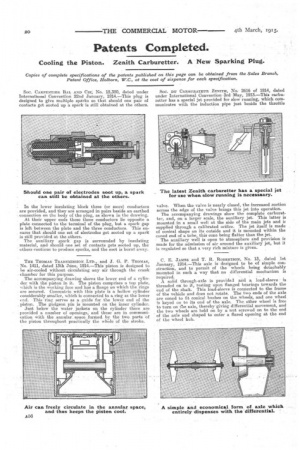
SOC. CARPENTIER BAL AND CIE; No. 15,380, dated under International Convention 22nd January, 1914.—This plug is designed to give multiple spsrks so that should one pair of contacts get sooted up a spark is still obtained at the others.
• In the lower insulating block three (or more) conductors are provided, and they are arranged in pairs beside an earthed • connection on the body of the plug, as shown in the drawing. At their upper ends these three conductors lie opposite a plate connected to the terminal of the plug, but a spark gap is left between the plate and the three conductors. This ensures that should one set of electrodes get sooted up a spark is still provided at the others.
The auxiliary spark gap is surrounded by insulating material, and should one set of contacts gets booted up, the others continue to produce sparks, and the soot is burnt away.
THE THOMAS TRANSMISSION LTD., and J. G. P. THOMAS, • No. 1411,dated 13th 'June, 1914.—This piston is designed to be air-cooled without circulating any air through the crank chamber for this purpose.
The accompanying drawing shows the lower end of a cylinder with the piston in it. The piston comprises a top plate, which is the working face and has a flange on which the, rings are secured. Concentric with this plate is a hollow cylinder considerably smaller, which is corinected to a ring at the lower end. This ring serves as a guide•for the lower end of the . piston. . The gudgeon. pin is mounted on the inner cylinder. Just below the 'water jackets on the Cylinder there are provided a number of openings; and these are iii communication with the .annular, space iortned by the two parts of the piston throughout practically the whole of the stroke.
Soc. DU CARBURATEUR ZENITH, No. 2616 of 1914, dated under International Convention 3rd May, 1913.—This carburetter has a special jet provided for slow running, which communicates with the induction pipe just beside the throttle valve. When the valve is nearly closed, the increased suction across the edge of the valve brings this jet into operation. The accompanying drawings show the complete carburetter, and, on a larger scale, the auxiliary jet. This latter is mounted in a small well at the side of the main jets and it supplied through a calibrated orifice. The jet itself is made of conical shape on its outside and it is mounted within the coned end of a tube, this cone being flatter than the jet.
The auxiliary well is open to atmosphere and provision is made for the admission of air around the auxiliary jet, but it is regulated so that a very rich mixture is given.
C. E. JAMES and T. R. ROBERTSON, NO. 13, .dated 1st January, 1914.—This axle is designed to be of simple construction, and to permit of the wheels being detachably mounted in such a way that no differential mechanism is required. A solid through-axle is provide3 and a load-sleeve is threaded on to it, resting upon flanged bearings towards the end of the shaft. This load-sleeve is connected to the frame of the vehicle and does not rotate. The two ends of the axle are coned to fit conical bushes on the wheels, and one wheel is keyed on to its end of the axle. The other wheel is free to turn on file axle, thereby giving differential movement, and the two wheels are held on by a nut screwed on to the end of the axle and shaped to enter a flared opening at the end of the wheel hub.


