


BUIL NG BUS BODIES A BIG WAY
Page 40
Page 41
Page 42
If you've noticed an error in this article please click here to report it so we can fix it.
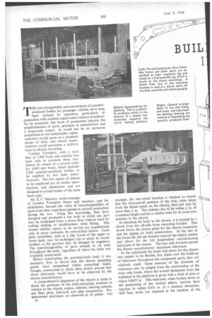
TLIE interchangeability and convenience of quantityproduced bodies for passenger vehicles have long been realized by operators, particularly in connection with accident repairs and overhaul procedure. To be economic, this form of production requires the standardization of parts, precision in manufacture and a large-scale .output. It would not be an economic proposition to the bodybuilder unless operators would agree on a standard design of body and chassis manufacturers could guarantee a uniform body-to-chassis mounting.
London Transport, with a total fleet of 7,000 buses and coaches, has been able to promote these conditions by reason of a current order for 4,000 new buses, which includes 2,000 quantity-produced bodies, to be supplied by two body manufacturers. The two makes of chassis to be employed are of similar specifications and dimensions and are designed to accept bodies of the same basic type.
Mr. E. C. Ottoway, works manager of London Transport (buses and coaches), and his technicians, learned the value of interchangeability of parts from their experience gained in aircraft production during the war. Using this knowledge, they have designed and produced a bus body in which any part may be exchanged from a stores float without need for cutting, drilling Or modifications when fitting. This system enables repairs to be carried out expeditiously and, in many instances, by semi-skilled labour. Complete assemblies, Such as a side frame of the upper or lower deck, may be exchanged just as easily by coachbuilder's as the gearbox may be changed by engineers. The interchangeability of parts extends to all units throughout the body, regardless of where the body was originally constructed..
Before constructing the precision-built body it was necessary, first, to ensure that the chassis mounting points. were maintained within prescribed limits. Gauges, ,constructed to check these points, proved that closer tolerances would have to be observed by the chassis manufacturers. .
A comprehensive inspection of the chassis is made to check the positions of the ,body-mounting brackets 'in relation to the wheels; engine, radiator, steering column. cab • floor plate, fuel-tank and• pipe connections, Predetermined tolerances are observedat all pbhits. "Far
,b4 example, the rear-wheel location is checked to ensure that the fore-and-aft position of the axle, when taken from the datum point on the chassis, does not vary by more than in. The radiator has to be within i in. of a nominal height and has a similar limit for its transverse position in the chassis.
In attaching the body to the chassis, it is located by a dowel from the off-side front mounting bracket. This dowel ferms the datum point for the chassis inspection and the jigging for body construction. At the rear of the frame the off-side bracket controls the lateral centres and allows for the full 'longitudinal manufacturing tolerances, of the chassis The near-side brackets permit the chassis manufacturers' maximum tolerances.
To the uninitiated the limits laid down for the chassis may appear to be ftexible, but, taken over the build-up of tolerances throughout the component parts, they are relatively, small. Some measure of the closeness of tolerances may be judged from the construction of the body side frame,. where the overall dimension from the bulkhead to the platform is given with a limit of plus or minus 0.0625 in This tolerance, when broken down to the positioning of the vertical pillars, restricts their location to within 0.011 hi., of a nominal dimension. ' Still finer limits are reqUired in the location of the
brackets supporting these pillars, and dimensions with a tolerance of plus or minus 0.002 in. and 0.004 in are specified.
Obviously, these line limits are necessary, as they provide the only means for promoting interchangeability, and, provided that the bodies are built on full-scale jigs, construction is speedier and less complicated than by previous methods. Jigs for the quantity-production body can be made at a relatively low cost, and although two concerns are at present supplying bodies to London Transport it has not been necessary to duplicate all the tools.
These bodies are being constructed by Park Royal Vehicles, Ltd., London, N.W.10. and Weymanns, Ltd., Addlestone, Surrey. A representative of "The Commercial Motor observed the quantity-production system in use at the former concern's works. where up to 10 bodies per week are being built.
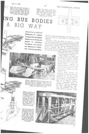
Pillars, struts, brackets and other parts of the body frame are jig-drilled and cut before being offered up as a sub-assembly, so that eventually the entire frame is built up in Meccano fashion_ T hese component parts are offered up on jigs for assembling the floor, inter-decking, sides, roof, cab, bulkhead, front, rear frame, platform and riser Units
from these jigs are later mated together on a finalassembly arrangement, which is gauged to the prescribed overall tolerances.
The all-steel platform riser is of scientific and rigid construction. It is designed to carry the rear platform, thus dispensing with the normal chassis rear extension and effecting an overall weight reduction. Stress panels formed in the lower saloon and from the destination box of the upper-saloon side frame add further to the rigidity of the platform-carrying pillars. At the opposite end of the lower deck the bulkhead panel is also of all-steel construction and is well reinforced with struts and stiffener brackets.
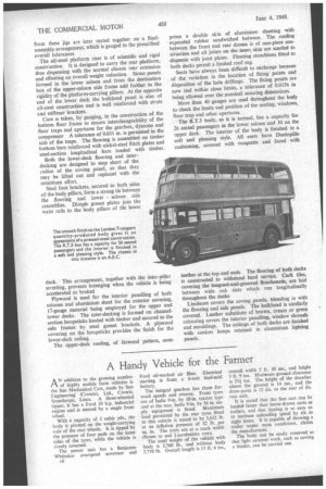
Care is taken, by gauging, in the construction of the bottom floor frame to ensure interchangeability of the floor traps and apertures for the gearbox, dynamo and compressor A tolerance of 0.031 in. is permitted in the size of the traps. The flooring is assembled on timber bottom bars reinforced with nickel-steel flitch plates and steel-section longitudinal bars loaded with timber.
Both the lower-deck flooring and interdecking are designed to stop short of the radius of the coving panel, so that they may be lifted out and replaced with the minimum effort.
Steel foot brackets, secured to both sides of the body pillars, form a strong tie between the flooring and lower saloon side assemblies. Dimple gusset plates join the waist rails to the body pillars of the lower deck. This arrangement, together with the inter-pillar strutting, prevents lozenging when the vehicle is being accelerated or braked Plywood is used for the interior panelling of both . saloons and aluminium sheet for the exterior covering, 17-gauge material being employed for the upper and lower decks. The inter-decking is formed on channelsection hoopsticks loaded with timber and secured to the side frames by steel gusset brackets. A plywood covering on the hoopsticks provides the finish for the lower-deck ceiling.
The upper-deck roofing, of licwood pattern, corn prises a double skin of aluminium sheeting with expanded rubber sandwiched between. The roofing between the front and rear domes is of one-piece construction and all joints on the inner skin are scarfed to dispense with joint plates. Floating stanchions fitted to both decks permit a limited roof sag.
Seats have always been difficult to exchange because of the variation in the location of fixing points and disposition of the hole drillings. The fixing points are now tied within close limits, a tolerance of 0.0156 in being allowed over the nominal securing dimensions.
More than 40 gauges are used throughout the body to check the limits and position of the seating, windows, floor trap and other apertures.
• The R.T.3 body, as it is termed, has a capacity for 26 seated passengers in the lower saloon and 30 on the upper deck. The interior of the body is finished in a soft and pleasing style. All seats have Dunlopillo cushioning, covered with moquette and faced with leather at the top and ends. The flooring of both decks is constructed to withstand hard service. Cork tiles, covering the tongued-and-grooved floorboards, are laid between wide oak slats which run longitudinally throughout the decks Linoleum covers the coving panels, blending in with the flooring and side panels. The bulkhead is similarly covered. Leather substitute of brown, cream or green colouring covers the interior panelling, window shrouds and mouldings. The ceilings of both decks are finished with sunken lamps retained in aluminium lighting panels.