


The Octopus ;ets a Standard fOr "Heavies"
Page 30
Page 31
Page 32
Page 33
If you've noticed an error in this article please click here to report it so we can fix it.
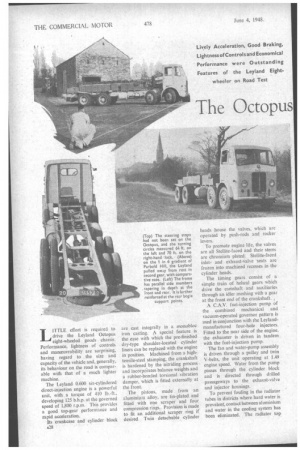
L1 FTLE effort is required to drive the Leyland Octopus eight-wheeled goods chassis. Performance, lightness of controls and manceuvrability are surprising, having regard to the size and capacity of the vehicle and, generally, its behaviour on the road is comparable with that of a much lighter machine.
The Leyland 0.600 six-cylinclered direct-injection engine is a powerful unit, with .a torque of 410 lb.-ft., developing 125 b.h.p. at the governed speed of 1,800 r.p.rn. This provides a good top-gear performance and rapid acceleration.
Its crankcase and cylinder block A28 are cast integrally in a monobloc iron casting. A special feature is the ease with which the pre-finished dry-type shoulder-located cylinder liners can be replaced with the engine in position. Machined from a hightensile-steel stamping, the crankshaft is hardened by the nitriding process and incorpdrates balance weights and a rubber-bonded torsional vibration damper, which is fitted externally at the front.
The pistons, made from an aluminium alloy, are tin-plated and fitted with one scraper and four compression rings. Provision is made to fit an additional scraper ring if desired Twin detachable cylinder heads house the valves, which are operated by push-rods and rocker levers.
To promote engine life, the valves are all Stellite-faced and their stems are chromium plated. Stellite-faced inletand exhaust-valve -seats are frozen into machined recesses in the cylinder heads.
The timing gears consist of a simple train of helical gears which drive the camshaft and auxiliaries through an idler meshing with a gear at the front end of the crankshaft , A C.A.V. fuel-injection pump of the combined mechanical and vacuum-operated governor pattern is used in conjunction with the Leylandmanufactured four-hole injectors. Fitted to the near side of the engine, the exhauster is driven in tandem with the fuel-injection pump.
The fan and water-pump assembly is driven through a pulley and twin V-bells, the unit operating at 1.49 engine speed. Water from the pump passes through the cylinder block and is directed through drilled passageways to the exhaust-valve and injector housings.
To prevent fouling in the radiator tubes in districts where hard water is prevalent, contact between aluminium and water in the cooling system has been eliminated. The radiator top tank is a sheet-brass pressing and the bottom tank is a gunmetal casting. The •cooling stack comprises a number of Still tubes, which may be easily removed for cleaning.
Engine, clutch and gearbox are of unit construction and are carried in the frame by a flexible mounting at the front end and by a banjo-pattern cross-member at the rear.
The large-diameter clutch is well ventilated and easy to detach. The facings are slotted radially, and these slots, in conjunction with holes drilled in the flywheel, induce a current of cooling air which assists in maintaining the mechanism at a reasonable temperature and in prolonging the life of the facings. Adjustment for wear is simple and positive, permitting full thickness of the facings • to be utilized before renewal is necessary.
Fifth, fourth and third gears are in constant mesh, fourth and third speeds being helical gears to promote quietness in operation.
The foremost feature of this box is the method of maintaining a positive supply of oil through the mainshaft bearings. Oil is picked up from the sump by one of the gears and is fed through grooves and drillings to the mainshaft bearings and constant-mesh gears. Provision is made for a power take-off from the top of the gearbox, which will transmit full engine torque, or a 10 h.p. take-off, which can be positioned on the near side of the box. Arrangements are also made for a tyre pump to be fitted,
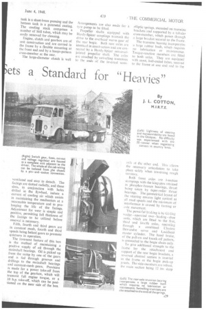
Propeller shafts equipped with Hardy-Spicer couplings transmit the drive to the overhead worm gear of the rear bogie. Both rear axles are identical in -consti action and are connected by a Hardy-Spicer universaljointed propeller shaft. The axles are attached by swivelling trunnions to the ends of the inverted semi
elliptic springs, mounted on trunnion brackets and supported by a tubular cross-member, which passes through a large bracket secured to the frame.
The trunnion bearing incorporates a large rubber bush, which requires no lubrication or maintenance. Torque-reaction members are fitted to both axles. They are equipped with stout, ball-ended tubes, secured to the frame at one end and to the axle at the other end. This allows the necessary articulation to take place safely when traversing rough territory.
Both front axles are I-section stampings with the king-pins retained in phosphor-bronze bearings, thrust being taken by taper-roller thrust bearings. The geometrical layout of the steering ensures light control at all road speeds and the minimum of interference is caused by turning or axle movement,
The powerful braking is by Girling wedge operated two leading shoe units, which are fitted to (he first, third and fourth axles, operating through a combined Clayton Dewandre servo and Lockheed master cylinder. The hand brake, of the pull-on and knock-off pattern, is connected to the bogie shoes only.
To give additional strength to the 11-3rne for the attachment and support of the rear bogie brackets, a reversed channel section is inserted in the frame at the bogie pick-up points. The side-members are robust, the main section being 12 ins. deep
with 3-in, flanges and a thickness of 0.3125 in.
The cab is an all-metal structure embracing the mudguards, engine bonnet and lamps, and is flexibly
mounted at the front. Good visibility is provided by the deep Windscreen and the cab is well ventilated. The driver's seat is adjustable, whilst the mate's seat may be easily removed to provide accessibility to the engine.
The test chassis had passed through the routine works test and had only a small mileage to its credit. A check On the weighbridge
A30 revealed that the running weight was slightly over the legal limit.
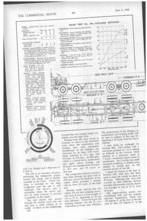
Starting from the main works at Leyland, we drove to the Ormskirk road, where the acceleration and braking tests were conducted. Acceleration of the Octopus was abnormal for its class, 0-20 m.p.h. being achieved in 21.1 secs. and 30 m.p.h. in 42.8 secs. In fifth gear, which is a direct drive, acceleration was again above average and 20 m.p.h. was reached from 10 m.p.h. in 18.5 secs. and 30 m.p.h. in 40.9 secs.
The comparison between acceleration times through the gears and in fifth gear proves the flexibility of the engine, which provided a smooth take-up from 10 rn.p.h, in the high gear.
Braking results showed that the vehicle did not lack stopping power, and from 20 m.p.h. it was brought to rest in 19 ft., equivalent to 70 per cent. efficiency. From 30 m.p.h. the stopping distance was 46A ft., corresponding to 64 per cent. efficiency. The performance of the Octopus in acceleration and braking could well be used in support of the case for legalizing a 30 m.p.h. limit for heavy vehicles.
I next made an onslaught on Parbold Hill. This incline, with a maximum gradient of I in 6, offered no difficulty to the Leyland, which climbed at a minimum speed of 7 m.p.h.—maximum engine speed in second gear. On a further test under stop-start conditions, it climbed away steadily in second gear on the severest section of the hill.
I tested the brakes at the foot of Parbold Hill, after they had been used to keep the vehicle in check to 30 m.p.h. Although they were well warmed up, their efficiency showed but little deterioration and the chassis was broughtto rest in 52 ft. from 30 m.p.h.
The engine-cooling system was functioning well, and the radiator top-tank temperature, which was 154 degrees F. at the foot of the hill, rose to only 155 degrees F. at the top. Atmospheric temperature at the time was 41 degrees F. The bonnet covers were removed at the top of the hill to check the oil tentperatures, and with the engine idling the draught from the fan was of hurricane force in the cab. Doubtless this is contributory to the efficiency of the cooling system.
Lubricating-oil temperatures taken under this adverse condition showed the engine oil to be 130 degrees F., gearbox 108 degrees F., middle axle
126 degree's F. and rear axle 128 degrees F. Considering the difficult nature of the climb, the temperatures afford a safe margin for operation of the vehicle under any climatic condition,
The fuel-consumption test was taken on a section of the ManchesterPreston road. This course is, perhaps, favourable to a consumption test and w as covered mainly in top gear. Gradients which would normally enforce a change to an intermediate gear on a less-powerful chassis were taken in direct drive and, with the exception of two traffic-light delays, the test was completed in top gear Fuel consumption for the course was 9.2 m.p.g. at an average speed of 25.7 m.p.h., a creditable performance for an overladen eight-wheeler.
We returned to Leyland through second-class country roads with many difficult bends, where I was able to appreciate the suspension and exceptional lightness of the steering.