


An All-hydraulic Transmission
Page 84
If you've noticed an error in this article please click here to report it so we can fix it.
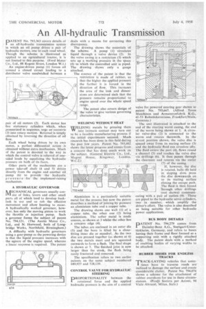
PATENT No. 793,363 covers details of an all-hydraulic transmission system in which an oil pump drives a pair of hydraulic motors, one to each road wheel. Though the scheme is illustrated as applied to an agricultural tractor, it is not limited to this purpose. (Ford Motor Co., Ltd., 88 Regent Street, London W.1.)
An engine-driven pump (1) forces oil around a closed circuit leading to a distributor valve sandwiched between a pair of oil motors (2). Each niotor has five stationary cylinders which, when pressurized in sequence, urge an'eceentric (3) into rotary motion. Reversal is Simply obtained by reversing the direction of oil flow.
Each wheel being driven by its own motor, a perfect differential action is obtained without extra mechanism. Much of the patent is devoted to the way in which the control valve is relieved of onesided loads by equalizing., the hydraulic pressure on both of its faces.
Other parts of the mechanism are a power take-off shaft (4 and 5) driven directly from the engine and another oil pump (6) to provide the hydraulic pressure-for the implemen t-rai sing mechanism.
A HYDRAULIC GOVERNOR
NAECHANICAL governors usually con0'1 sist of links, levers and other small parts all of which tend to develop backlash in use and so rob the effective movement and allow hunting to occur. A hydraulically worked governor, however, has only the moving piston to work the throttle or injection pump. Such a governor forms the subject of patent No. 794,121. (The Austin Motor Co., Ltd., and N. Horwood, both of Longbridge Works, Northfield, Birmingham.)
A difficulty with hydraulic governors using a gear-pump as the powering device is that the liquid pressure increases with the square of the engine speed, whereas a linear response is required. The patent deals with a means for correcting this discrepancy.
The drawing shows the essentials of the scheme, A pump (1) circulates liquid through a valve device (2). In the valve casing is a restriction (3) which sets up a working pressuie in the space (4) to which the controlled unit is piped. The drawing shows only a gauge attached.
The essence of the patent is that the restriction is made of rubber, so that the higher the applied pressure the farther it is forced in the direction of flow. This increases the area of the leak and dimensions are determined such that the pressure remains proportional to engine speed over the whole speed range, The patent also covers design of the valve td give various governing characteristics.
WELDING WITHOUT HEAT
WELDING metals by pressing them VV into intimate contact may turn out to be a feasible manufacturing process if the initial experiments succeed. Much research has been done in this field during the past few years. Patent No. 793,402 shows the latest progress and comes from a concern that has done much Work on the subject. (General Electric Co., Ltd., Magnet House,. .1(ingsway. London, Aluminium is a particularly suitable metal for the process but now the patent describes a method of joining by pressure an aluminium tube and a copper tube.
The drawing shows one wall (1) of 4 copper tube, the other one (2) being aluminium. The softer metal is made convex, as shown at 3 whilst the other has ,a concave edge (4).
The tubes are enclosed in an outer die (5) and the bore is filled by a closefitting inner die or mandrel. As the two d:es are pressed together (as shown at 6) the two metals meet and are squeezed outwards to form a flash. The final shape is shown at 7. The finished joint is now larger than the stock, the flash being
easily fractured and removed.
The specification refers to two earlier patents on the same subject numbered 689,927 and 728,139.
CONTROL VALVE FOR HYDRAULIC STEERING
DROPORTIONALITY between the rotational force and the applied hydraulic pressure is the aim of a control
valve for powered steering gear 'shown in patent No. 793,667. (Alfred Teves Maschinen und Armaturenfabrik K.G., 41-53 RehsttickerstraSse, Frankfurt/Main, Germany.)
The unit illustrated is attached to the -end of the steering worni casing, the end of the worm being shown at 1. A circular valve-disc (2) is connected to the worm and rotates therewith. In the at-rest position shown, the valve disc is spaced away from its mating surface (3) and the hydraulic fluid can circulate idly. The fluid enters the port (4), flows round a channel (5) and reaches the'valve disc via drillings (6). It then passes through the clearance and returns via the outlet (7) of the casing.
• " If, however, the disc is rotated, bails (8) held in sloping slots press the disc downwards on to its Mating surface closing the escape path. The fluid is then forced through other drillings (not shown) comrnunieating with a pair of outlets (9). These are piped to the hydraulic servo cylinders, two in number, which amplify the driver's effort. The valve is also described as being suitable for other hydraulic power applications.
Wyv NN.`k
BUS BODY DETAILS
PATENT No. 794,279 comes from Daimler-Benz A.G., Stuttgart-Unterthrkheim, Germany, and refers to buses having their frame and floor formed as a supporting unit with a rigidly attached body. The patent deals with a method of enabling bodies of varying widths to be attached.
RUBBER SHOES FOR ENDLESS TRACKS
TTRACK-LAYING vehicles that sometimes have to traverse roads are inclined to damage the surface and create considerable clatter. Patent No. 794,074 shows a scheme for the attachment of rubber overshoes for use in these circumstances. (Pire/1i Societa per Azioni, 94 Viale Abruzzi, Milan, Italy.)