


A Petrol-injection Pump
Page 62
If you've noticed an error in this article please click here to report it so we can fix it.
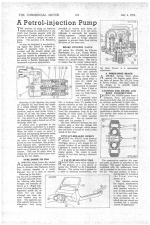
THE practice of using an injection 1 pump instead of a carburetter is one which may become popular with the larger sizes of engine, and in patent No. 671.706 is shown a design for such a pump. The patentee is R. Bienaime, Paris.
As may be imagined, a non-lubricating liquid like petrol is difficult to handle if excessive wear is to be avoided, and the present design gets over the lubrication problem in an ingenious manner by pumping oil only, and using the pressure pulse to displace the petrol, a flexible diaphragm being interposed to prevent intermixture.
Referring to the drawing, the casing (1) contains oil, and forms BIS intake of a simple plunger pump (2). The plunger is operated by an overhead eccentric, and on each stroke forces a charge of oil into the lower chamber where it distends a flexible diaphragm (3). The petrol is on the other side of the diaphragm, and is forced out of the discharge Valve -(4).
A release port is provided in the petrol chamber, controlled by a poppet valve (5) operated by an overhead cam. When the valve is open, no petrol is delivered, the pumping movement being absorbed by a flexible diaphragm (6). As the shape of the cam (7) shows. the valve is closed for only a short period in every revolution, thus giving a short injection time. Quantitative control is afforded by putting the two camshafts out of phase by a greater or less amount. This can be easily done by sliding one of the two helical gears connecting the two shafts.
TYRE INSIDE ITS RIM
ASPRUNG wheel forms the subject of patent No. 670,165, which comes from 0. Alvistur, San Francisco, U.S.A. The resilient member is a smalldiameter tyre as is used on aircraft.
Referring to the drawing, the tyre (1) comprises a normal tube and cover, the inflating tube being brought out .centrally as shown at 2. Rigid side • plates (3) form guides for segmental pieces (4); of which five are used, although any other de. sired number may be used. The segments can slide radially between the side-plates, slots being A40 provided to receive their bolts (5). An outer tread (6) is in one piece, although it surrounds the separate sliding segments. Leather pads (not shown) are used to bridge adjacent segments to prevent them from cutting the cover of the inner tyre.
BRAKE CONTROL VALVE IN patent No. 670,098, the Clayton 1Dewandre Co., Ltd., Titanic Works, Lincoln, discloses an improved control valve for working the compressed-air brakes of a tractor-trailer. The aim is to ensure that the trailer brakes apply a little before those of the tractor so as to prevent over-running, The Unit controls both sets of brakes, those on the trailer • being piped from a • port (1), whilst the tractor brakes are connected to another (2). Ports 3 lead to individual air reservoirs on both tractor and trailer.
In operation, when rod 4 is pulled to the left, a rocking beam (5) 'pushes both pistons similarly so that the action of the top one only need be described. The piston first closes off the brake port from the atmosphere (veal 6) by the meeting of valve faces (7) and then opens the valve 8 which supplies compressed air. The air reaches the brake port via passage 9.
The only difference between the two control units is that the springs (10) differ slightly in strength, which means that one valve is bound to work a little ahead of the other.
CONTACT-BREAKER DESIGN
PATENT No. 670,917, from General
Motors Corporation, Detroit, Michigan, shows a new design for the contact breaker of an ignition system. Lightness is aimed at so that bounce will not occur at the highest attainable engine speeds. The rocker is made mainly of steel sheet having a thickness of 0.01 in.
A VALVE RE-SEATING TOOL
RE-CUTTING worn valve seatings is the purpose of a tool shown in patent No. 670,459 by, H. Chacksfield, Harrow. The cutting tool is guided by a pilot to maintain concentricity, and A 'FHREE-SHOE. BRAKE ABRAKE having three shoes spaced 120 degrees apart forms the basis of patent No. 671,211, from E. Perrin, France. The main object of the design is to provide highly efficient performance.
CASTINGS FOR FRAME AND BODY CONSTRUCTION
PATENT No. 670,070 comes from J. 1 Gregoire, Paris, and discloses a chassis-cum-body that can be produced by castings, preferably in light alloy.
In the original patent No. 459,491, the same inventor covered the principle of using castings for frame construction, employing a number of cross-members. The present idea seeks to remove the need for them.
The construction employs five separate units, as shown in assembly in the drawing. The upper dashboard (1) is combined with the windscreen frame and is attached to the lower dash member (2). This part projects to form a bolting face (3) to receive the front casting shown at 4.
This member carries the engine, transmission and springs. The lower dash member receives a pair of side-members (5) at its rear face, and these, in turn, carry the rearmost extremities (6) to which the rear wheels are attached via a suitable system of suspension.