


Patents Completed.
Page 22
If you've noticed an error in this article please click here to report it so we can fix it.
IGNITION DEVICE.—Electric Ignition Co., Ltd.—No. 17,812, dated 8th August, 1906.—The main object of this device is to so construct the make-andbreak device that the action of the trembler shall be continuous when running at high speeds. This is effected by a springcontrolled, pivoted arm (7) which rests upon a camshaft (6). This arm makes electrical contact with a second spring. controlled, pivoted arm (14). When run. fling slowly, the arm (7) drops into the -recesses between the cams and moves away from the arm (14), as the latter is limited in its downward movement by a stop (16). When running fast, however, the arm (7) does not have time to descend
into the recesses between the cams on the shaft, and, thus, the circuit is maintained practically unbroken, and the trembler is kept in continuous action.
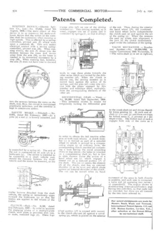
SAFETY BRAKE. —Dibsdall.—No. 9,005, dated 6th February, 1907.—In a yoke (a) a rod (e) is loosely mounted, and is controlled by a spring (e). The end of the rod is connected by an arm (f) to a brake-arm (g). The device is intended to be connected to a draft vehicle and, should the distance between the draftvehicle and the trailer he lessened, or the trailer become detached from the draft vehicle, the spring (e) immediately urges forward the brake-arm (g) so that the brakes are applied to the wheels of the trailer.
CLUTCH.—Hall.—No. 4,f:93, dated 21st February, 1907.—In order to separate the engaging plates of a multiple-plate clutch, each plate is provided with one, or more, extended lugs (h). These lugs engage pins (m2) on one of the driving members (e). This driving member, as is usual, engages one set of plates and is controlled by springs (i), so that it always tends to urge these plates towards the other series which are carried by the driving member (a2). When the clutch is thrown out, the driving member .(e) is moved back against the action of its springs, and the pins (nit) come into contact with the plates engaged by this member and withdraw them, separately, from the corresponding elements of the other set.
DIFFERENTIAL GEAR. — Viney. — No. 20,266, dated 12th September, 1906. —This invention relates to means for temporarily locking the differential gear
in order to ob am n the full tractive adhesion of both road wheels. A clutch member (a) is formed as part of a sprocket wheel (b) which is secured to a compensating sleeve (e) of ordinary form, the corresponding clutch member (d) comprising a boss having the usual projecting claws or dog pieces ; the latter is mounted on a compensating shaft (e), but is free to slide thereon tinder the action of a hand wheel nut (f) which engages a thread cut on a reduced. portion (el) of the shaft. The nut (f) enters the element (d) of the clutch, and has an external shoulder (f) at its inner end which abuts against an internal shoulder of the clutch. The nut can be moved when its hand wheel portion (f21 is rotated with resnect to the clutch element (d) against a spiral spring (g), which is placed on the exterior of the nut. Thus, during the rotatior the hand wheel (f2), the combined and hand wheel move independently the clutch part (d) and against the act of the spring CO. When the recesses the part (a) rotate into alignment vs the part (d) the clutch immediately gages under the influence of the spring VALVE MECHANISM. — Boudre; and Another.—No. 25,630/1906, da (under Convention) 18th November, if —The valve-shaft (c) is set at right-an to the crank-shaft (a) and driven therefr by worm gearing (e). At each end of shaft (c) is a cam (g) and these are enga( by forked arms (i, j) pivoted at / anc respectively. The forked end of each a engages both side of the cams so t:
movement of the arms in both directio is positive, and each arm is connected a valve rod (p) operating two valves ( v) respectively. The engine shown is double-acting internal-combustion engi having two cylinders, so that eight valv are provided, but these are all controll by the two cams referred to.