CERAMICS REDUCE CLUTCH ABUSE
Page 84
Page 85
Page 86
Page 87
Page 88
If you've noticed an error in this article please click here to report it so we can fix it.
New clutch materials have almost taken over as OE fitment. Colin Sowman looks at the advantages
When it comes to friction linings, brakes are easily inspected and replaced, but the clutch is a different kettle of fish. It is, perhaps, this problem that has prevented operators from fully accepting the materials.
The introduction of non-asbestos and ceramic friction lining materials was brought about to overcome different problems and so it is not surprising that their properties are different. Ceramics were introduced to cope with extreme situations and abuse in a better way than 0--of the existing asbestos-based
materials. Non-asbestos materials are being introduced solely to remove the potentially harmful asbestos.
To assess the relative merits of the materials and their acceptance in the market we visited specialist commercial vehicle clutch producer Lipe. The company has been manufacturing clutches for 17 years and is best known for its pull-type units, turning out over 20,000 new or reconditioned units a year using all the friction materials.
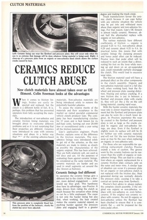
Lipe's application engineer, Frank Procter, explains some of the difference in the friction materials. The nonasbestos linings were introduced solely to get rid of the asbestos, so the new materials are made to mimic as closely as possible the characteristics of the organic original. This has been achieved. They are both relatively soft, are used as full discs and can. for the purposes of evaluating them against ceramic linings, be considered as the same material. The ceramic materials are harder and are used in small segments set around the disc (known as buttons).
Ceramic linings feel different
In operation the ceramic linings give a different feel to the clutch; it has a sharper, more defined engagement — some would say they grab. This harshness does have its advantages, says Proctor. It stops drivers from riding the clutch as much because the sensation when doing so can be a little unpleasant. The cause is not only the harder lining but also that, when working, the heat created makes the ceramic material expand, so pushing harder against the pressure plate and engaging itself to a greater
degree and making the truck creep.
Truck manufacturers favour the ceramic clutch because it can cope better with any extreme situation the vehicle may be put into and withstand more abuse than organic and non-asbestos linings. For that reason, Lipe's OE fitment is almost totally ceramic. However, about half the aftermarket replace with organic or non-asbestos.
The various materials have different coefficients of friction — organic is around 0.25 to 0.3, non-asbestos about 0.29 and ceramic about 0.35 to 0.4. In practical terms this means that with ceramic linings the clamping pressure and hence pedal effort can be reduced. Proctor fears that pedal effort will he reduced to such an extent that a driver, resting his foot on the lever while moving up and down on an air-suspended seat, could repeatedly partially disengage the clutch. This would lead to excessive wear rates.
The friction material used will have a profound effect on the other components in the clutch assembly. Organic and non-asbestos materials used in a full disc will, when working hard, heat the flywheel and pressure plate causing distortion, blueing and surface cracking. If a new friction disc is put in between a flywheel and pressure plate with cracks in, they will act like a file on the soft lining material, causing rapid wear.
With the harder ceramic materials the wear rate is slower requiring less adjustment but the flywheel and pressure plate can also be worn (to a much lesser degree). In Proctors experience the wear lip created in the flywheel and pressure plate is not as large as the cracks created by organic and non-asbestos linings, are deep. Even if the flywheel is slightly worn its surface will still be fit for further use with ceramic materials and will not 'file' the new friction lining away as may be the case when replacing an organic or non-asbestos unit.
For those who are responsible for specifying replacement clutches Proctor sounds a note of caution. The groove worn by the ceramic buttons can be narrower than the width of organic or nonasbestos linings. This can lead to a situation where an organic replacement for a ceramic fricition plate contacts only on the outer and inner rims. A similar type of situation can occur if a pressure plate for an organic or non-asbestos clutch is not replaced with the friction disc. Heat generated during use normally distorts the pressure plate, causing it to take a conical set (point away from flywheel).
Proctor's best advice is: always replace the complete clutch assembly, if the original was organic or non-asbestos, replace with non-asbestos or, even better, ceramic. If the original was ceramic replace with ceramic. Do not fit organic or non-asbestos unless the flywheel has been checked to ensure that it is completely flat — and be prepared for the extra pedal effort.
SCAN LA'S trucks have long appealed to drivers who appreciate the comfort offered inside the imposing cabs. While the 143 is undoubtedly the flagship of the range, the 113 with its 11-litre engine is the bread and butter machine preferred by many fleets.
The introduction of the Series-3 saw the level of driver comfort improve still further, but what about maintenance considerations?
Scania has just announced that oildrain periods have been extended from 20,000km (12,500 miles) to 30,000km (18,750 miles). These, along with other changes in the schedules, mean a 25% reduction in service requirement over the Series 2.
The new schedules apply to all Series-3 vehicles since introduction. However, those working off-road may require more attention.
Workshop went along to Scantrucks at Purfleet to see what is involved in the new maintenance schedules and followed a 368kW (360hp) 113 Topline 4x2 tractive unit through the Mfi service. This is the middle of the three levels of service on Scania vehicles. Our vehicle was 15 months' old, had covered 56,000km (35,000 miles) and had just returned from the bodyshop after having some damage repaired.
Services are now carried out at 30,000km (18,750 miles) intervals in the sequence M3, M6, M3, M12 with an (MX) inspection and manual brake adjustment check between each. Standard times for the normal M3, M6 and M12 services are 4.4, 5.8 and 8.4 hours respectively. There are additional items on the initial M3 and M6 services.
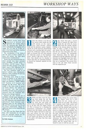
Our fitter was Ray Chant who has been with Scantrucks for 11 years and has attended almost all the courses run by the manufacturer. Once the vehicle is over the pit, the service starts inside the cab with checks on the wipers, horn, hand throttle, exhaust brake and the demister system. Depleating the air in the reservoirs should bring a buzzer and a warning light into action. Check the windscreen washers with the lights on because this will then activate the wash-wipe system on the headlamp lenses. Series-3 cabs have electric windows; they should also be checked to ensure that they are operating properly, as should the hydraulic adjuster for the headlamp.
1
2 Ray Chant then gets a second
filter to operate the lights from inside the cab while he checks
them from the outside. Besides looking in the obvious places for blown bulbs, he takes a couple of steps back and checks that the marker lights set into the sun visor strip above the windscreen are working. The tachograph must illuminate when the lights are switched on and the indicators and highintensity rear fog-lights must have dashmounted warning lights to show when they are in operation. The second fitter stays in the cab while Chant decends into the inspection pit.
3 While one fitter rocks the steer
ing from inside the cab, the other checks the ball joints on the drop arm and track rod ends for play on split gaiters. Chant prefers to do this with the engine turned off. This is because he is checking the mechanical components not actualy trying to turn the wheels, and the vibration of the engine will tend to mask any play and remove the feel from the steering-wheel. Sealed-for-life ball joints do not require any grease, but any split in the gaiter will mean that they need replacement.
4 Before letting the second fitter go, Chant, while he is still
down the pit, carries out a check for air leaks. The Scania has a separate trailer brake control and the second fitter operates this in conjunction with the normal hand and foot brakes to check all the air systems. If there is a leak on a brake chamber, the air can normally be felt escaping around the seals. Should there be a leak, it is possible that the diaphragm has split, and normally this can be renewed — otherwise, the whole brake chamber should be replaced. All was well with our vehicle and the second fitter was released to carry on with his own job.
5 There is no need to remove the
brake drums on the M6 service — this is required only on the
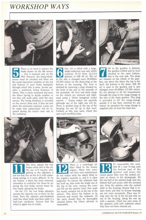
M12. However, the lining thicknesses must be checked and there are the usual inpsection windows in the top and bottom of each brake backplate through which this is done. Scania specifies a minimum lining thicitoess of lOmm. This is easily measured and saves the fitters having to decide weather or not they will work safely until the next. service. The lining thickness is recorded on the service sheet and, if they are just above the minimum required, a note can be made that replacement will be required during the truck's next visit to the workshop. 6 Our 113 is fitted with a large,
single-reduction rear axle which contains 10-12 litres (2.2-2.6
gallons) of SAE 90 oil. The oil in the axle is changed every 60,000km (37,500 miles) via the drain plug at the bottom of the housing. The level is checked by removing a plug situated on the front of the axle to the nearside of the propshaft. All level and drain plugs on the vehicle are removed and tightened using a 19mm hexagonal socket wrench — Scania makes one specially although any of the right size will do. There is another plug at the top of the housing. Do not fill up to that level_ Unlikely as this may seem, Chant has seen such overfilled axles. 7 Oil in the gearbox is drained,
the gearbox refilled and its level checked in the same fashion, this is the next task. The plugs are situated on the offside of the gearbox, one above the other; the top is the level, the bottom is the drain. SAE 90 oil is used in the gearbox and is also changed every 60,000km (37,500 miles). Do not attempt to fill the transmission through the plug in the range-change at the rear of the main gearbox. This plug is provided to fill the range-change quickly if it has been removed for any reason. In operation the range-change is supplied with oil from the main box.
8 The level plugs and sump plug
each has a magnet fitted to pre vent swarf floating around in the workings and causing damage. These magnets should always be cleaned whenever the plug is removed. There is no need to put any sealant or washers on the level plugs when reinserting them because they seal themselves on a taper. Chant moves on to drain the sump. This plug does use a sealing device in the form of an aluminium washer which requires replacing only when it becomes damaged. With a new filter fitted, the sump needs about 25 litres (51/2 gallons) of 15W 40 oil to fill it.
9 Moving out from the pit, the
wheel bearings are given a check. This is done by jacking the axle up and then spinning each wheel while listening to the bearing. Any problem will cause a harshness, rumble or clicking sound. The front wheels have grease-filled hearings, the rear are oil-filled — each will he checked in turn. A bar is inserted through the front wheels and levered upwards to detect any play in the kingpins. Chant prefers to do this before greasing, which could mask any defect.
10 When the fitter has en
sured that there are no de fects that would require
the brake drums to be removed, the brakes can be adjusted. The easiest way to do this is to put the front wheels onto full lock while the axle is still jacked up, and get inside the mudwing ahead of the wheel. Rotate the adjuster clockwise until the wheel is locked and then undo it about a half turn, checking that the wheel is free to move again. Take this opportunity to check that the wheel will turn fully onto its lock stop and that it does not foul any pipework or linkages.
11 The fitter adjusts the rear
brakes while still in the pit.
On our 4x2 tractive unit, getting to the adjusters is not too bad, but on the 6x4 with underslung springs it is more difficult. If, for any reason, a drum has been removed, remember to centralise the shoes by applying the foot brake several times before finally adjuating the brake.
On the 113, the rear brake adjusters operate the opposite way to those on the front. Turn the adjuster anti-clockwise until the wheel locks and then undo it a half-turn clockwise. Ensure that the wheel is again free to rotate. 12 There is a centrifugal oil
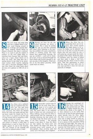
filter fitted to the Scania engine. Many who carry out their own maintenance do not realise what the object fitted to the engine's nearside is, and it is often neglected. To remove the sediment that has built up, frist undo the single nut at the top of the cone, remove the cover and lift out the spinner itself. Now undo the round, serrated nut at the top of the spinner. This allows the bottom to be removed and reveals the sediment. All the parts should then be thoroughly cleaned before the fitters attempt to reassemble.
13 To reassemble the unit,
first fit a new 0-ring onto the bottom part of the
spinner and place the course gauze filter over the central column as shown in the photograph. Fit the top half of the spinner body onto the bottom half and secure with the serrated nut. Drop the spinner onto the central shaft in the housing. Ensure that it rotates freely and that its bronze bearings are not worn excessively. Place new 0ring onto the lip of the lid and refit on top of the housing, doing the nut up with a spanner. Chart has seen some of the spinners solid with sediment where they have not been cleaned out. 14 Two filters and a sediment
trap are located in the Sca nia's fuel line and these were the next items to receive attention. The filters are situated below the main fuel pump and are slotted down inside the chassis rail. To remove them it is easiest to use the type of strap wrench that is turned by a halfinch-drive socket-set wrench.
While the filter bowl is glass, Chart still prefers to remove it every time. A thumb-wheel is used to keep the bowl tightly against its seal in the housing. The seal remains in the housing and need not be replaced unless it leaks.
15 Renewable canister-type fil
ters are used. these have a smear of oil or grease put onto the seal before refitting. The gauze filter in the sediment bowl is blown out with compressed air. When refitting, ensure that the filter located properly into the underside of its housing, otherwise the fuel system will not bleed. Undo the bleed screw on top of the filter housing — the priming pump is just above it. Once the filters are full, tighten the bleed screw and then slacken the banjo bolt above the priming pump (with spanner on in photograph). Keep priming until fuel comes out of the banjo, then retighten.
16 Besides the centrifugal oil
filter there is also a renew able canister-type one. This is hidden behind the chassis rails on the offside of the engine. It is often referred to as the turbo filter because the oil feed for the turbocharger comes directly from the filter. Again, this filter is not easy to get to and the same type of strap wrench as used earlier is required. Smear a small amount of oil or grease on the seal before fitting and doing up hand tight. The sump can now be refilled through the rocker box if required, but Chant prefers to wait until the cab is lowered and to use the filler at the front and check on the dipstick.
17 Early Series-3 models need
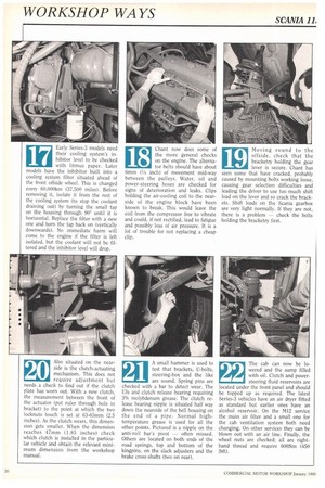
their cooling system's in hibitor level to be checked with litmus paper. Later models have the inhibitor built into a cooling system filter situated ahead of the front offside wheel. This is changed every 60,000km (37,500 miles). Before removing it, isolate it from the rest of the cooling system (to stop the coolant draining out) by turning the small tap on the housing through 90° until it is horizontal. Replace the filter with a new one and turn the tap back on (vertically downwards). No immediate harm will come to the engine if the filter is left isolated, but the coolant will not be filtered and the inhibitor level will drop.
18 Chant now does some of
the more general checks on the engine. The alterna
tor belts should have about 6mm (1/4 inch) of movement mid-way between the pulleys. Water, oil and power-steering hoses are checked for signs of deterioration and leaks. Clips holding the air-cooling coil to the nearside of the engine block have been known to break. This would leave the coil from the compressor free to vibrate and could, if not rectified, lead to fatigue and possibly loss of air pressure. It is a lot of trouble for not replacing a cheap clip. 19 Moving round to the
offside, check that the bracketry holding the gear lever is secure. Chant has seen some that have cracked, probably caused by mounting bolts working loose, causing gear selection difficulties and leading the driver to use too much shift load on the lever and so crack the brackets. Shift loads on the Scania gearbox are very light normally. If they are not, there is a problem — check the bolts holding the bracketry first.
20 Also situated on the near
side is the clutch-actuating mechanism. This does not require adjustment but needs a check to find out if the clutch plate has worn out. With a new clutch, the measurement between the front of the actuator (put ruler through hole in bracket) to the point at which the two locknuts touch is set at 63-65mm (2.5 inches). As the clutch wears, this dimension gets smaller. When the dimension reaches 47mm (1.85 inches) check which clutch is installed in the particular vehicle and obtain the relevant minimum dimension from the workshop manual. A small hammer is used to test that brackets, U-bolts, steering-box and the like are sound. Spring pins are checked with a bar to detect wear. The Ins and clutch release bearing requiring 3% molybdenum grease. The clutch release bearing nipple is situated half way down the nearside of the bell housing on the end of a pipe. Normal hightemperature grease is used for all the other points. Pictured is a nipple on the anti-roll bar's pivot — often missed. Others are located on both ends of the road springs, top and bottom of the kingpins, on the slack adjusters and the brake cross-shafts (two on rear).
21
The cab can now be lowered and the sump filled with oil. Clutch and powersteering fluid reservoirs are located under the front panel and should be topped up as required. The latest Series-3 vehicles have an air dryer fitted as standard but earlier ones have an alcohol reservoir. On the M12 service the main air filter and a small one for the cab ventilation system both need changing. On other services they can be blown out with an air line. Finally, the wheel nuts are checked; all are righthand thread and require 600Nm (450 lbft).
22


