


A NEW SPARKING PLUG.
Page 70
If you've noticed an error in this article please click here to report it so we can fix it.
A Résumé of Recently Published Patent Specifications.
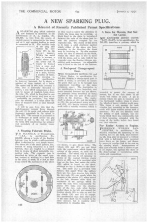
ASPARKING plug which embodies new features is described in the specification of R. L. Aspden, No. 201,820. A wire from the source of electric energy is connected to the inner coil. at 1. and another leading to earth is connected to H. The metallic body of the plug (B) carries the electrode (C) in the usual manner. Within the metal body is screwed a metal sleeve (ID), the lower end of which is formed into a cone, and the body of which is made in the form of a helix, having a number of turns. The drawing in the specification, is, however, incorrect, for it shows a number of rings instead of a helix. The upper end of this helix becomes a tube, and is internally threaded to receive a nut which compresses a liner and, by mean g of washer, holds down the tube (P), which is described in one paragraph as of metal, and later on as " preferably an insulator," -but whatever the material :s it must allow the lines of magnetic force to pass .through it easily.
It will be seen from this that the high-frequency current flows through the coil (0) to earth, and induces highfrequency potentials in the spiral or helix (D). The current so generated in discharges to earth across the gap between E and C, the Coil (G) and the helix (T)) constituting the primary and secondary of an electric transformer.
A Floating Fulcrum Brake. F B. FLANIGAN, of Pennsylvania,
U.S.A., in specification No. 240,155, shows a brake of the floating fulcrum type, in which a self-energizing effect is obtained by very simple means. The shoes are of the usual pattern, but, instead of being connected to a fixed fulcrum, they are coupled to a hinged link by means of short adjustable connecting rods. The expander cam is described as being of the usual type, but, instead of working in a fixed hole in the plate, it works in a slot so that it can follow the movement of the shoes
as they tend to follow the direction in which the drum may be revolving. A block fixed to the plate is introduced between the ends of the shoes just inside the position occupied by the expander cam. The object of this block is to form a solid abutment against which either of the shoes can bear, according to the direction the drum may he revolving in. By this arrangement one shoe is arrested by the block, whilst the other shoe is free to move with the drum, and to take with it the expander cam, the floating fulcrum permitting such movement. An adjustable stop is fitted to the link of the fulcrum.
A Fool-proof Change-speed Gear.
THE WOLSELEY MOTOR CO. and
Oliver Baden, in specification No. 261,488, describe a change-speed gear in which a means is provided to ensure the gears that are to be brought into engagement travelling at the same peripheral spee;.. The description in the specification is very imperfect, and many essential features are not shown, the principle being described as being applied to only one pair of the gears shown in the drawing, The engine shaft is shown at (A) and the layshaft at (B), the second-speed gears are (C) and (11), (C) having internal teeth to mesh with a suitable member, which is
lot shown. •tJ give direct drive. The wheels (E) and (I') are not fitted with the contrivance which forms the subject of the patent so need not be described. The wheel (0) is loose on the shaft, and can be set spinning by means of the conical friction clutch shown at (H), but it is provided with dogs on the face that meets the collar (M), which is keyed to the shaft, although no key is shown in the drawing. The shaft (A) is provided with Splines, but apart from the splines there are two deep grooves into which the two rods (N) can recede when the Pressure of the pinion (C), when moved to the left, becomes more than the resistance of the springs which lie under the rods (N) ; consequently the pinion (C) rides over the slanting ends of the two rods after having pushed them to the left and caused the friction clutch (H) to take up and the dog clutch (M) and (0) to engage. The specification says that other gears on the same shaft can be treated in the same • manner, but it requires some imagination to visualize this.
A Gate for Motors, But Not for Cattle.
SIR KENNETH IRWIN CROSSLEY, BART., in his specification No. 201,873, describes a gateway which is
intended to permit the passage of motors, but is one that cattle of all kinds will refuse to pass. A pit is formed where the gate is required, and two horizontal ladders cross it where the wheels of motor vehicles would pass. Thisforms a safe passage for such vehicles, but, according to the inventor, cattle will never venture across such a structure. '%1j are not familiar with the habits of such animals, but one would think there was considerable risk of their becoming entangled with the rungs of the ladder before they found out their mistake.
For Easier Access to Engine.
FREDERICK WILLIAM LAN CHESTER, in specification No. 261,874, describes the mounting of the steering box on the dash, and connecting the drop arm by means of a vertical link with a bell-crank lever mounted lower down on the frame, and thence by means of another link to the arm on the steering wheel. Arrangements of this type certainly make it easier to get at an engine, but against this there is the disadvantage cf introducing, extra oints. Mid connections.