


Patents Completed.
Page 22
If you've noticed an error in this article please click here to report it so we can fix it.
Complete specifications of the following patents will be sent to any address in the United Kingdom upon receipt of eightpence per copy at the Sale Branch, Patent Office, Holborn, W.C.
Argyll's Detachable Wheel.
Argylls, Ltd.—No. 1,970, dated 26th January, 1911.—The detachable wheel here described is of the type in which the detachable part is carried by a removable hub part, which fits over a permanent
hub part on the shaft of the vehicle. The drive is transmitted to the detachable part by means of conically-headed bolts. The removable hub part is placed on the permanent hub part, and the ends of these conical bolts are fitted into corresponding holes in the removable hub part. The wheel is then pushed on until the first thread on the removable hub engages with the thread on the per manent hub. A spanner is then applied to the cam ring by which the locking mechanism is controlled. The rotation of the cam ring screws on the wheel, and the slots for the spanners arc SO arranged that, in turning the cam ring to such a position as will allow the removal of the spanner, the locking arrangement is brought into operation.
Improved Clutch Operation.
Saver Clutch Co. and Drake.—No. 834, dated 12th January, 1911.—This specification describes a modification of the Warner type of clutch described in Patents Nes. 15,153 of 1907 and 14,114 of 1908. The two members
comprise a central cylindrical member and a pair of bands bearing on it, which latter can be tightened by a toggle mechanism and so cause the band to grip the cylindrical member and lock the respective members of
the clutch together. The present improvement consists in operating the toggle mechanism by links which extend inwards towards the hub of the wheel and are there operated upon by plungers. Since these plungers lie close to the hub and not, as in previous constructions, remote from the axial centre, canting cannot take place; thus the difficulties on account of jamming are avoided,
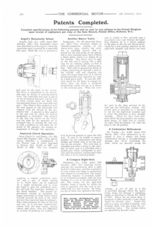
Another Sleeve Valve.
Lamplough.—No. 39, dated 2nd January, 1911,--This invention relates to internal-combustion engines of the sleeve-valve type, wherein the cylinder is extended beyond that re. quired for the full stroke of the piston, and in such extended space there is fitted a sleeve piston which is a sliding fit in the cylinder. The sleeve valve is split on one side and is sprung like a split ring for an ordinary piston, so that it gives a tight joint under working pressure. The valve is operated by means of a finger projecting in through a port in the cylinder wall and engaging the valve, the finger being fast on a vertical spring-controlled rod, operated by cams on a half-speed shaft. To provide sufficient metal for the finger to engage the sleeve valve, the latter is machined eccentrically inside and out as is shown on the sectional plan. When the valve is in its lowest position it. opens the inlet port. It rises to its middle or neutral position for the compression and firing strokes and finally rises to its top position for the exhaust.. The valve may be extended and form a lining to the cylinder, in which ease it is provided with a second port which corresponds in position with the primary exhaust port when the valve is in its neutral position.
A Compact Sight-feed, Wakefield.—No. 1,374, dated 18th January, 1911.—The drawings accompanying this specification show a sight feed for a lubricator, and this is stated to he very simple and cheap in construction and compact in arrangement. The liquidccntaining chamber is mounted rigidly on or is formed integrally with the plug member of a cock in the lubrication circuit.. The casing for the sight feed chamber forms a handle by which the cock is operated, and the cock is provided with two sets of ports. Hy bringing one of these into operation the lubri
cant is caused to flow upwards past a non-return valve and through the sightfeed chamber up to a lateral passage in the plug at the top and thence downwards by a side passage adjacent to the sight-feed chamber and thence out from the port in the plug member of the cock into the lubrication conduit. The second port is provided as a bye-pass to cut out the sight-feed chamber and to allow the lubricant to flow straight
through. There are thus three positions which the plug member can occupy, these being: (1) sight feed in circuit; (2) sight feed bye-passed; (3) with the plug in the off position.
A Carburetter Refinement.
De Veulles.—No. 6,348, dated 14th March, 1911.—This carburetter is designed to give a simple and cheap construction having a straight-through passage and valves controlling the same which are mumble across the passage. A row of jets or a slot is provided through which the petrol issues, being fed through a regulating nipple as described in Patent No. 13,372 of 1911. Above the jet outlet there is arranged to slide vertically a tube which forms the throttle valve. Inside this tube is a plug, provided if desired, with bevelled edges, and this forms the air
controlling valve. The various valves are operated by Bowden wires.