 1
1 2
2 3
3 4
4 5
5 6
6 7
7 8
8 9
9 10
10 11
11 12
12 13
13 14
14 15
15 16
16 17
17 18
18 19
19 20
20 21
21 22
22 23
23 24
24 25
25 26
26 27
27 28
28 29
29 30
30 31
31 32
32 33
33 34
34 35
35 36
36 37
37 38
38 39
39 40
40 41
41 42
42 43
43 44
44 45
45 46
46 47
47 48
48 49
49 50
50 51
51 52
52 53
53 54
54 55
55 56
56 57
57 58
58 59
59 60
60 61
61 62
62 63
63 64
64 65
65 66
66 67
67 68
68 69
69 70
70 71
71 72
72 73
73 74
74 75
75 76
76 77
77 78
78 79
79 80
80 81
81 82
82 83
83 84
84 85
85 86
86 87
87 88
88 89
89 90
90 91
91 92
92 93
93 94
94 95
95 96
96 97
97 98
98 99
99 100
100 101
101 102
102 103
103 104
104 105
105 106
106 107
107 108
108 109
109 110
110 111
111 112
112 113
113 114
114 115
115 116
116 117
117 118
118 119
119 120
120 121
121 122
122 123
123 124
124 125
125 126
126 127
127 128
128 129
129 130
130 131
131 132
132 133
133 134
134 135
135 136
136 137
137 138
138 139
139 140
140 141
141 142
142 road and workshop
Page 88
If you've noticed an error in this article please click here to report it so we can fix it.
by Handyman
Auto-electrics for the mechanic (7)
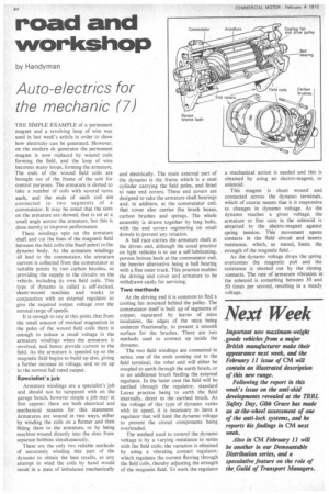
THE SIMPLE EXAMPLE of a permanent magnet and a revolving loop of wire was used in last week's article in order to show how electricity can be generated. However, on the Modern dc generator the permanent magnet is now replaced by wound coils forming the field, and the loop of •wire becomes many loops, forming the armature. The ends of the wound field coils are brought out of the frame of the unit for control purposes. The armature is slotted to take a number of coils with several turns each, and the ends of each coil are connected to two segments of a commutator. It may be noted that the slots on the armature are skewed, that is set at a small angle across the armature, but this is done merely to improve performance.
These windings spin on the armature shaft and cut the lines of the magnetic field between the field coils (the fixed poles) in the dynamo body. As the armature windings all lead to the commutator, the armature current is collected from the commutator at suitable points by two carbon brushes, so providing the supply to the circuits on the vehicle, including its own field coils. This type of dynamo is called a self-excited, shunt-wound machine and works in conjunction with an external regulator to give the required output voltage over the normal range of speeds.
It is enough to say at this point, that from the small amount of residual magnetism in the poles of the wound field coils there is enough to induce a small voltage in the armature windings when the armature is revolved, and hence provide current to the field. As the armature is speeded up so the magnetic field begins to build up also, giving a further increase in voltage, and so on up to the normal full rated output.
Specialist's job Armature windings are a specialist's job and should not be tampered with on the garage bench, however simple a job may at first appear; there are both electrical and mechanical reasons for this statement. Armatures are wound in two ways, either by winding the coils on a former and then fitting them to the armature, or by being machine-wound directly into the slots from separate bobbins simultaneously.
These are the only two reliable methods of accurately winding this part of the dynamo to obtain the best results, as any attempt to wind the coils by hand would result in a state of imbalance mechanically and electrically. The main external part of the dynamo is the frame which is asteel cylinder carrying the field poles, and fitted to take end covers. These end covers are designed to take the armature shaft bearings and, in addition, at the commutator end, that cover also carries the brush boxes, carbon brushes and springs. The whole assembly is drawn together by long bolts, with the end covers registering on small dowels to prevent any rotation.
A ball race carries the armature shaft at the driven end, although the usual practice on light vehicles is to use a self-lubricating, porous bronze bush at the commutator end, the heavier alternative being a ball bearing with a free outer track. This practice enables the driving end cover and armature to be withdrawn easily for servicing.
Two methods At the driving end it is common to find a cooling fan mounted behind the pulley. The commutator itself is built up of segments of copper, separated by leaves of mica insulation, the edges of the mica being undercut fractionally, to present a smooth surface for the brushes. There are two methods used to connect up inside the dynamo.
The two field windings are connected in series, one of the ends coming out to the field terminal; the other end will either be coupled to earth through the earth brush, or to an additional brush feeding the external regulator. In the latter case the field will be earthed through the regulator, standard Lucas practice being to earth the field internally, direct to the earthed brush. As the voltage of this type of dynamo varies with its speed, it is necessary to have a regulator that will limit the dynamo voltage to prevent the circuit components being overloaded.
The method used to control the dynamo voltage is by a varying resistance in series with the field coils; the variation is obtained by using a vibrating contact regulator, which regulates the current flowing through the field coils, thereby adjusting the strength of the magnetic field. To work the regulator a mechanical action is needed and this is obtained by using an electro-magnet, or solenoid.
This magnet is shunt wound and connected across the dynamo terminals, which of course means that it is responsive to changes in dynamo voltage. As the dynamo reaches a given voltage, the armature or free core in the solenoid is attracted to the electro-magnet against spring tension. This movement opens contacts in the field circuit and inserts resistance, which, as stated, limits the, strength of the magnetic field. • As the dynamo voltage drops the spring overcomes the magnetic pull and the resistance is shorted out by the closing contacts. The rate of armature vibration in the solenoid is something between 30 and 50 times per second, resulting in a steady voltage.