 1
1 2
2 3
3 4
4 5
5 6
6 7
7 8
8 9
9 10
10 11
11 12
12 13
13 14
14 15
15 16
16 17
17 18
18 19
19 20
20 21
21 22
22 23
23 24
24 25
25 26
26 27
27 28
28 29
29 30
30 31
31 32
32 33
33 34
34 35
35 36
36 37
37 38
38 39
39 40
40 41
41 42
42 43
43 44
44 45
45 46
46 47
47 48
48 49
49 50
50 51
51 52
52 53
53 54
54 55
55 56
56 57
57 58
58 59
59 60
60 61
61 62
62 63
63 64
64 65
65 66
66 67
67 68
68 69
69 70
70 71
71 72
72 73
73 74
74 75
75 76
76 77
77 78
78 79
79 80
80 81
81 82
82 83
83 84
84 85
85 86
86 87
87 88
88 89
89 90
90 91
91 92
92 93
93 94
94 95
95 96
96 97
97 98
98 99
99 100
100 101
101 102
102 103
103 104
104 105
105 106
106 107
107 108
108 109
109 110
110 111
111 112
112 113
113 114
114 115
115 116
116 117
117 118
118 119
119 120
120 121
121 122
122 123
123 124
124 125
125 126
126 127
127 128
128 129
129 130
130 131
131 132
132 133
133 134
134 135
135 136
136 137
137 138
138 139
139 140
140 141
141 142
142 143
143 144
144 145
145 146
146 147
147 148
148 149
149 150
150 151
151 152
152 153
153 154
154 155
155 156
156 157
157 158
158 159
159 160
160 161
161 162
162 163
163 164
164 165
165 166
166 167
167 168
168 169
169 170
170 171
171 172
172 173
173 174
174 175
175 176
176 177
177 178
178 179
179 180
180 181
181 182
182 183
183 184
184 185
185 186
186 187
187 188
188 189
189 190
190 191
191 192
192 193
193 194
194 195
195 196
196 ROAD TANKERS
Page 102
Page 103
Page 104
Page 109
If you've noticed an error in this article please click here to report it so we can fix it.
their design and construction
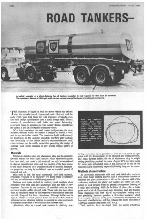
THE transport of liquids in bulk by motor vehicle has existed since the introduction of commercial trucks. But not until the early 1930s were bulk tanks for road transport of liquids given any more design consideration than a static storage tank. Then a number of manufacturers with boiler and vessel fabricating experience began to specialize in road tanker vehicles, considering the tank as a unit of a composite transport vehicle.
Of all load containers the road tanker shell provides the most desirable features which will enable a designer to match a tank unit to any particular chassis. The maximum liquid load can only be distributed as the designer intended, therefore axle loadings can be exactly to the chassis maker's recommendations, tank cross sections can be widely varied thus permitting the design of compact tank shells resulting in low overall vehicle centre of gravity.
Materials
Mild steel, stainless steel and aluminium alloy are the currently specified metals for bulk liquid tankers. Glass reinforced plastic has been used, but tanks in this material can only be considered to date as experimental units, and the reaction of the base resins to the many products to be transported and the material mechanical properties can only be established over an extended period of research and test.
Mild steel is still the most commonly used tank material, principally because of its relatively low price, ready availability and long establishment as a fabricating material.
Stainless steel tanks are built in relatively small numbers when compared with mild steel and aluminium alloy but fulfil a very important function in the transport of materials such as some corrosive liquids, edible oils and milk. These tanks arp more often than not insulated either for the retention or exclusion of heat and specially designed for inner cleanliness. Although initial cost is high the ability to switch product loads and the need for a tank to withstand severe cleaning methods is essential to some operators; in these instances there is no substitute for stainless steel.
Aluminium alloy as a road tank material is relatively new, having come into more general use over the last seven to eight years with the development of the shielded arc welding process. The main purpose behind the use of aluminium alloy is weight saving, permitting payload increases of up to 20% over steel tanks for some large articulated units. A big increase in the use of this material can be confidently expected following the g.v.w. increases.
Methods of construction
As previously mentioned mild steel tank fabrication methods stem from boiler making practice and a considerable amount of material and plate preparation is left to the inherent skill of the tradesmen involved; the plater and electric arc welder are competent to work straight from the general arrangement drawing of a tank and mounting. With the facilities of plate rolls, a brake press and a set of die-pressed ends, divisions, pads and flanges, these tradesmen will with aid of oxy-acetylene cutting torch and planishing hammer produce a first-class container which over a period of some thirty years of technical development and improved manufacturing skill has reduced the barrel thickness of 4,000 gal. capacity steel tanks to 12 s.w.g.
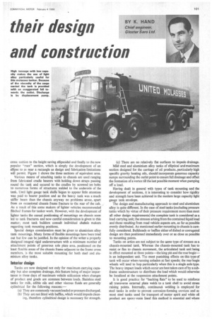
Tank sections have developed from the simple cylindrical cross section to the height-saving ellipsoidal and finally to the now popular "max" section, which is simply the development of an ellipse to as near a rectangle as design and fabrication limitations will permit. Figure 1 shows the three sections of equivalent area.
Various means of attaching tanks to chassis are used ranging from fabricated cradle bearers with holding down straps passing round the tank and secured to the cradles by screwed tee bolts to numerous forms of structures welded to the underside of the tank. Until light gauge tank shells began to appear little attention was paid to bearer position and as the heavy tank was a much stiffer beam than the chassis anyway no problems arose, apart from an occasional chassis frame fracture to the rear of the cab. , As a result of this some makers of lighter vehicles recommended flitched frames for tanker work. However, with the development of lighter tanks the casual positioning of mountings on chassis soon led to tank fractures and now careful consideration is given to this matter; most tank builders consult individual chassis makers regarding tank mounting positions.
Special design consideration must be given to aluminium alloy tank mountings. Many forms of flexible mountings have been tried out but few can be justified. In the opinion of the writer a properly designed integral rigid understructure with a minimum number of attachment points of generous sole plate area, positioned on the least flexible areas of the chassis frame adjacent to the frame cross members. is the most suitable mounting for both steel and aluminium alloy tanks.
Interior design Tanks are now designed not only for maximum carrying capacity but also complete drainage, this feature being of major importance in these days of maximum vehicle utilization when changes of product and grade are common between loads. Stainless steel tanks for milk, edible oils and other viscous fluids are generally cylindrical for the following reasons:—
(a) They are commonly vacuum loaded or pressure discharged.
(b) They are not fitted with baffles, which would impede cleaning, therefore cylindrical design is necessary for strength. (c) There are no relatively flat surfaces to impede drainage.
Mild steel and aluminium alloy tanks of elliptical and maximum section designed for the carriage of oil products, particularly high specific gravity heating oils, should incorporate generous capacity sumps surrounding the outlet point to ensure full drainage and offset the formation of a vortex till the last possible moment when pumping off a load.
Having dealt in general with types of tank mounting and the development of sections, it is interesting to consider how rigidity and strength have been achieved in the modern large capacity light gauge tank envelope.
The design and manufacturing approach to steel and aluminium alloy is quite different. In the case of steel tanks (excluding pressure tanks which by virtue of their pressure requirement more than meet all other design requirements) the complete tank is considered as a load carrying unit; the stresses arising from the contained liquid load and those resulting from road vehicle aspects are, as far as possible evenly distributed. As mentioned earlier mounting to chassis is carefully considered. Bulkheads or baffles either of dished or corrugated design are then positioned immediately over or as close as possible to mounting points.
Tanks on artics are not subject to the same type of stresses as a chassis-mounted tank. Whereas the chassis-mounted tank has to resist or flex to chassis movement, the articulated tank unit being in effect mounted at three points—the king pin and the rearbogieis an independent unit. The most punishing effects on this type of tank will occur when running unladen at fast speeds; the rear bogie wheels will tend to hop particularly when this is a single axle type. The heavy impact loads which occur are best taken care of by a subframe understructure to distribute the load which would otherwise be localized at the suspension attachment points.
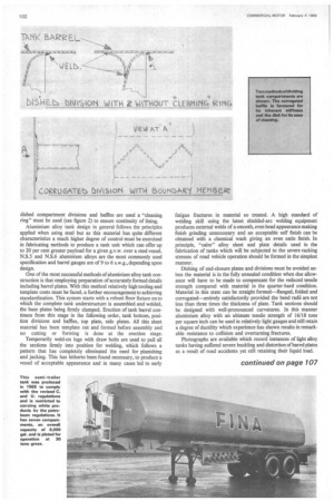
It is good practice for "backing flats" to be used to reinforce all transverse external plate welds to a tank shell to avoid stress raising points. Internally, continuou§ welding is employed for steel tanks in order to prevent corrosion-forming crevices and as most steel tanks used for transport of motor spirit and white oil product are epoxy-resin lined this method is essential and where dished compartment divisions and baffles are used a "cleaning ring" must be used (see figure 2) to ensure continuity of lining.
Aluminium alloy tank design in general follows the principles applied when using steel but as this material has quite different characteristics a much higher degree of control must be exercised in fabricating methods to produce a tank unit which can offer up to 20 per cent greater payload for a given g.v.w. over a steel vessel. N.S.5 and N.S.6 aluminium alloys are the most commonly used specification and barrel gauges are of 9 to 6 s.w.g., depending upon design.
One of the most successful methods of aluminium alloy tank construction is that employing preparation of accurately formed details including barrel plates. With this method relatively high tooling and template costs must be faced, a further encouragement to achieving standardization. This system starts with a robust floor fixture on to which the complete tank understructure is assembled and welded, the base plates being firmly clamped. Erection of tank barrel continues from this stage in the following order, tank bottom, position divisions and baffles, top plate, side plates. All this sheet material has been template cut and formed before assembly and no cutting or forming is done at the erection stage.
Temporarily weld-on lugs with draw bolts are used to pull all the sections firmly into position for welding, which follows a pattern that has completely eliminated the need for planishing and jacking. This has hitherto been found necessary, to produce a vessel of acceptable appearance and in many cases led to early fatigue fractures in material so treated. A high standard of welding skill using the latest shielded-arc welding equipment produces external welds of a smooth, even bead appearance making finish grinding unnecessary and an acceptable self finish can be obtained with a chemical wash giving an even satin finish. In principle, "calm" alloy sheet and plate details used in the fabrication of tanks which will be subjected to the severe racking stresses of road vehicle operation should be formed in the simplest manner.
Dishing of end-closure plates and divisions must be avoided unless the material is in the fully annealed condition when due allowance will have to be made to compensate for the reduced tensile strength compared with material in the quarter-hard condition. Material in this state can be straight formed—flanged, folded and corrugated—entirely satisfactorily provided the bend radii are not less than three times the thickness of plate. Tank sections should be designed with well-pronounced curvatures. In this manner aluminium alloy with an ultimate tensile strength of 16/18 tons per square inch can be used in relatively light gauges and still retain a degree of ductility which experience has shown results in remarkable resistance to collision and overturning fractures.
Photographs are available which record instances of light alloy tanks having suffered severe buckling and distortion of barrel plates as a result of road accidents yet still retaining their liquid load.
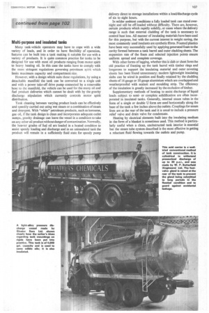
Multi-purpose and insulated tanks Many tank-vehicle operators may have to cope with a wide variety of loads, and in order to have flexibility of operation, features can be built into a tank making it suitable for use with a variety of products. It is quite common practice for tanks to be designed for use with most oil products ranging from motor spirit to heavy heating oil. In this case the tanks have to comply with the more stringent regulations governing petroleum spirit which limits maximum capacity and compartment size.
However, with a design which suits these regulations, by using a detachable manifold the tank can be converted to a single unit and with a power take-off drive pump connected by a removable hose to the manifold, the vehicle can be used for the many oil and fuel product deliveries which cannot be dealt with by the gravity discharge stipulation which currently controls motor spirit distribution.
Tank cleaning between varying product loads can be effectively and speedily carried out using wet steam or a combination of steam and detergent. With "white" petroleum products, such as kerosene, gas oil, if the tank design is clean and incorporates adequate outlet sumps, gravity drainage can leave the vessel in a condition to take on any other oil product without danger of contamination . Norm ally, the heavier grades of fuel oil are loaded hi a heated condition to assist speedy loading and discharge and in an uninsulated tank the product will remain in a sufficiently fluid state for speedy pump
delivery direct to storage installations within a load/discharge cycle of six to eight hours.
In milder ambient conditions a fully loaded tank can stand overnight and still be off-loaded without difficulty. There are, however, certain products which rapidly solidify, or cases where the delivery range is such that external cladding of the tank is necessary to control heat loss. All manner of insulating materials have been used for this purpose, but with the current interest in weight saving, the • most commonly used insulants are synthetic fibres. Foamed plastics have been very successfully used by applying generated foam to the cavity formed between a tank barrel and outer cladding sheets. The expansion rate of the foam and selected injection points ensure uniform spread and complete coverage.
With other forms of lagging, whether this is slab or sheet form the old practice of framing up the tank barrel with timber rings and longerons to support the insulating material and outer covering sheets has been found unnecessary; modern lightweight insulating slabs can be wired in position and finally retained by the cladding sheets of 16 gauge or 18 gauge aluminium which are overlapped and weatherproofed with sealant and moulding strip. The efficiency of the insulation is greatly increased by the exclusion of timber.
Supplementary methods of heating to assist discharge of liquid loads subject to semior complete solidification are often incorporated in insulated tanks. Generally, internal steam tubes in the form of a single or double U form are used horizontally along the base of the tank a few inches above the outlets. Couplings for steam lines are at the rear of the tank and it is usual to include a pressure relief valve and drain valve for condensate.
Heating by electrical elements built into the insulating medium in the form of a blanket is sometimes used. This method is particularly useful when a clean, unobstructed tank interior is essential but the steam tube system described is the most effective in getting a reluctant fluid flowing towards the outlets and pump.