


A Self-energizing Brake
Page 78
If you've noticed an error in this article please click here to report it so we can fix it.
1-1 A BRAKE that uses some of the
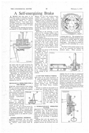
drum energy to intensify its action forms the subject of patent No. 720,257 (Kelsey-Hayes Wheel Co., Detroit, Michigan, U.S.A.). Two small shoes are first pressed into drum engagement and their movement is used to apply the main shoes.
Referring to the drawing, the hydraulic actuator (1) when 'energized spreads
the upper ends of a pair of -levers (2); this causes the auxiliary shoes, (3) to make contact with the moving drum_ The small shoes tend to move with the drum and in so doing turn cams (4) which thrust the main shoes into action.
Retraction is performed by four springs (5) which tend to pull in all the shoes. Adjusting nuts (6) govern the off position of the main shoes whilst the auxiliary ones are similarly adjusted by nuts (7).
MECHANICAL OPERATION FOR A
4 DISC BRAKE DETAIL improvements in disc brakes are covered in patent No. 717,308 (Girling Ltd., Kings Road, Birmingham,
11), In particular, the patent deals with a means for operating mechanically such brakes that are normally hydraulically worked.
In the drawing, 1 and 2 a r e t h e hydraulic plungers by which the friction pads are normally caused to bear on the rotary disc (3). As a second means for operation, a floating lever (4) can pull two plungers, 5 and 6, towards each other and so grip the disc independently of the hydraulic system. The scheme is intended mainly to be used for a parking brake.
.POWER-ASSISTED ittERING QERVO mechanism for use with 1,--isteering gear is the subject of patent No. 720,321, which comes from R.
Bishop, 145 The Vale, Golders Green, London, N.W.11, and others. The scheme refers particularly to the rackand-pinion type of steering mechanism.
When a steering column with a pinion on its end is turned to move a rack, the pinion will endeavour to move sideways in the opposite direction to the rack movement. Use is made of this fact to operate the power valve of the servo cylinder.
Referring to the drawing, 1 is the pinion on the steering column and 2 part of the rack. The rack is extended to the left to form the piston-rod of the servo cylinder (3).
The bottom bearing (4) of the column is a slack fit so that before the pinion moves the rack it first rocks over to one side or the other, taking up the small clearance in the bearing. When this occurs, the column slides a block (5) to the right or left against the action of a spring.
Although not shown in this drawing, the sliding block is connected by levers to the control valve, so that the manual movement of 'the column is immediately amplified by the servo cylinder. The arrangement is selflapping; that is, it cuts off the power as soon as the rack
has reached .posi.t ion corresponding to-the setting of the column.
A CLIP FOR VEHICLE WIRING
TO assist in the rapid attachment of cables and pipework is the purpose of a small fitting shown in patent No. 719,416, by E. Fernberg and Ferntol Patents, Ltd.,. 174 Gresham House, Old Broad Street, London, E.C.2.
Al] that is needed on the pan-el (1) is a small hole through which is pushed the spring clip (2). This is shown holding a pair of cables (3). The chip is made of parallel strip, but is provided with a pair of notches (4), which allow it to spring outwards and lock securely over the edges. of the hole.
A HYDRAULICALLY OPERATED CLUTCH
PATENT No. 720,022 (Hobbs Transmission, Ltd., 78 Russell Terrace, Leamington Spa), shows an improvement in an earlier design of hydraulic clutch, the aim being to prevent lag in operation by providing a pneumatic
spring. • • Dealing first with the general conStruction, the driven disc (1) can be gripped between the flywheel face and
a presser. plate (2). The gripping force is provided by hydraulic pressure when applied to an annular space (3), which is closed on one side by a flexible diaphragm. The pressure is created by a pump (4) and controlled by a valve (5).
The basis of the present patent is the use of air reservoirs (6) behind the pressure space. When pressure is
applied, the air in these is compressed and thus gives a smooth build-up. The area of the small passages connecting the liquid and air spaces is half that of the main liquid entry port, and the gentler-action is due to this. When the pressure is released, the compressed air facilitates the ejection of the liquid.
Other patents dealing with the Hobbs hydraulic clutch arc numbered 637,269, 637,251 and 628;499.