


Road Roller With a Vibrating Attachment
Page 26
If you've noticed an error in this article please click here to report it so we can fix it.
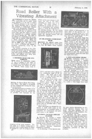
• ACCORDING to patent No. 608,043, Pia road-roller can be made much more effective if it be able to impart. a vibratory pressure to the road, and the patent describes such a machine. The patentee is ll'edershaab Maekinfabrik A/S, Brondersleve Denmark.
The drawing shows the outline of the machine which has, in addition to the usual front and rear rollers, a central, one supported in. a resilient manner, such as on springs (T). The roller is not drivenas, a road'-wheel. but is-provided; with an interior shaft fitted wilt a heavy eccentric masc. When the latter isrotated! by Vrehelle (2); at front 500 to 5,Efflefl r.p.m., the miler isset. into violent oscillatrprt and imparhe a beneficial compacting action to theroad material.
The resilient mounting of the roller effeetually prevents-' any Seriousshaking of the rest of the machine. lefieuntings other than springsare eleseribed robber bodies and inflhted tyres being both mentioned and illustrated.
A STEERING GEAR FOR LF.S. VEHICLES
'THE advent of independent suspen
sion, is leading to new ideas on the subject .of. Meeting. gears, and such a, scheme forms the subject of patent No: 609-356,. which comes from F.
Hicklibg, 36, DaviesRoad, West Bridgford; Meets. The object: is -tot Preivitle an easy, working' gear. having, the vitflie of irreversibility.
The thawing shows, an example Of the designin the simplest form. A steering 4 (Ii) extends across, the vehicle and ieprovided with'ball-ends for the receptionof the usual members: The rod slides -in a tubular casing and is provided. with a quick thread (2)which is engaged by a pin (3) acting. aaa nut.
e36 If the rod be now rotated, it will move one way or the other, according to which way it is turned. The rotary motion is produced by cutting the rod as for a wormwheel. and meshing iheoeit a worm (4) mounted on the steering column.. By this means, any shocks imparted by the rod wheels are resisted by the pin (3) and do not reachthe. steering column with any appreciable magnitude.
AN. OIL-ENGINE COMBUSTION HEAD
No: 609,349 comes from I E. 34'artlend and the Ford Motor CGS, Etti, aa, Regent Street, London, S.W.P, and deals with a design for the combustion, head of an oil engine. The chief aim is adequately to mix The fuel and the air by a swirling action.
The diawing shows both a plan and an elevation of the combustion space, whichis wedge shapedin section. The inlet valve (l), being, to. one side of the cylinder. sets upa considerable roiary swirl,
as indicated, hy, the amaws. This action occurs with a plain valve, calling for no otaeking devices which put up the cost of the valve andnetessitate keying devices to, prevent rotation. At top. dead centre thereis also. a considerable " squish " effect due to. the presence of a narrow space (2). The injector gives several jets of spray,. four being. shown in the drawing. Ae modification, instead of a: flat top, the piston: may. be provided with a recess (3) in its crown.
Other advantages araclaimed, fbr the layoute it lends itselfeasily to the accommodation of overhead calves, is convenient for water-spaces and! gives goodaccess to the injector.
GEARBOX COUPLED IMPULSE STARTER.
AMEANS for starting a vehicle engine by the stored energy of a low-powered electric motor, is shown in patent No. 608,318 by A. Sampietro, Hylande Hotel, Warwick Road, &eventry. The low-powered motor may be the ordinary dynamo, temporarily modified-by switching.
In the drawing, 1 is the dynamo-cum motor, which is belt-connected to the input shaft of the gearbox (2). An electrically operated clutch (3) is provided Between the engine and the gearbox; this is the main crutch.
Inoperation, the crutch being free, the motor is energized and rapidly spins the clutch. member upne a high speed. Where. awing to the. high speed; the motor current fella tee a certain value, arelayoperates and: switchesr an the clinch magnetizing. current. Thie connects the spinning clutch-rnemiter to the engine.; which is thus turned over by: the stored energy: Shourcli the engine fail to start, the electric: circuit will automatically repeat the cycle until
the engine dbes start. •
A SELF-ADJUSTINGBRAKE.
A BRAKE mechanism which automatically maintains a constant clearance between the shoes and. the drum, is shown. in patent No. 608358,
by J. Prate and Manley, both of Guildhall Buildings; Navigation Street, Birmingham, 2. The adjustment in! this case is performed. hydraulically.
In the drawing, I is the main hydraulic expander-which works in the usual way. Below this is a pair of hydraulic, cylinders (2)which' forms the adjusting means, The pistous of these cylinders, are. joined to. the gimes, by links (.3) and are limited in stroke by a collar (4) an-each pistnn. Thie.slides in a space a, little longer thanitself, the extra motion determining the permitted clearance between shoe and drum. The extra cylinders are not rigidly attached to the back-plate; they are held only, by friction.
In operation, the main expander spreads. the shoes, while the others move their pistons, outwardly up to the stop collars. Any further movement of the shoes. CRAMS the adjuster cylinders to be bodily dragged with them. On the return stroke, the shoes are arrested by the inner faces of the stop collars and stay there, the return springs being insufficiently powerful' to shift the cylinders.