


IS THIS THE PERFECT ENGINE MOUT
Page 10
Page 11
Page 12
If you've noticed an error in this article please click here to report it so we can fix it.
'INC SYSTEM?
By A. J. HIRST,
B.Sc., A.M.I.Mech.E.
THE examples tci which reference was made in the first part of -this article, published in last week's issue of " The Commercial Motor," serve to illustrate the general trend of engine mounting design during the 15, years following the introduction of floatingpower, but there were many other ideas, too numerous to deal with in this article, which worked out well in practice.
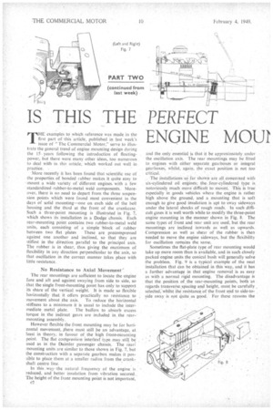
More recently it has been found that.scientific use Of the properties of bonded rubber makes it quite easy to ' mount a widevariety of different engines, with a few . standardized -rubber-to-metal weld components. Moreover, there is no need to depart from the three suspension points which were found most convenient in the days of solid mounting—one on each side of the bell housing and the third at the front of the crankcase. Such a three-point mounting is illustrated in Fig. 7, which shows its installation in a Dodge chassis. Etch. rear-mounting point contains two rubber-to-metal weld units, each consisting of a simple block of rubber between two flat plates These are precornpressed • against one another and inclined, so that they are stiffest in the direction parallel to the principal axis. The rubber is in shear, thus giving the maximum of flexibility in any direction perpendicular to the axis, so that oscillation in the correct manner takes place with little resistance.
No Resistance to Axial Movement'. . The rear mountings are sufficient to locate the 'engine fore and aft and against swaying from side to side, so that the single front-Mounting point has only to support its share of the vertical weight. It is made. so flexible horizontally that it offers practically no resistance. to movement about the axis. To reduce the horizontal stiffness to a minimum it is usual to include the inter.
mediate metal plate. The buffers to absorb excess torque in the indirect gears are included in„ the rear-
mounting assembly.. .
However flexible the front mounting may be for horizontal movement, /here must still be an advantage, at least in theory; in favotir of the' high frOnt-triounting point. The flat cornpreskion interleaf type may still be used as in the Daimler passenger chassis. The rear mounting units are similar to those shown in Fig. 7, but the construction with a separate gearbox makes it possible to place them at a smaller radius from the crankshaft centre line.
In this way, the natural freqiiency of the engine is . reduced, and better insulation from vibration secured... The height of the front mounting point is not important, and the only essential is that it be approximately under the oscillation axis. The rear mountings may be fitted to engines with either separate gearboxes or integral gearboxes, whilst, again, the exact position is not too
.
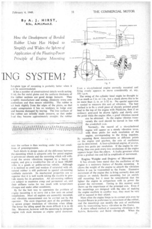
The installations so far Shown are all,concerned with six-cylindered oil engines; the four-cylindered type is notoriously much more difficult to mount. This is true especially in goods vehicles where the engine is rather high above the ground, and a mounting that is soft enough to give good insulation is apt to sway sideways under the lateral shocks of rough roads. In such difficult gases it is well worth while to modify the three-point engine mounting in the manner shown in Fig. 8. The same types of front and rear unit arc used, but the rear mountings are inclined inwards as well as upwards. Compression as well as shear of the rubber is then needed to move the engine sideways, but the flexibility for oscillation remains the same.
Sometimes the flat-plate type of rear mounting would take up more room than is available, and in such closely packed engine units the conical bush will generally solve
the problem. Fig. 9 is a typical example of the neat •• installation that Can be obtained in this way, and it has a -further advantage in that engine removal is as easy as with a normal rigid mounting. The disadvantage is that the position of the rear-mounting points, both as regards transverse spacing and height, must be carefully selected;whilst the resistance of the front end to side-toside sway is not quite as good. For these reasons the
flat-plate type of mounting is probably better when it can be accommodated.
• It has-a number of constructional details worth noting. First, the flat metal plates and the uniform thickness of the rubber sections are good design features. They sinplify manufacture and testing, eliminate stress concentrations and thus ensure reliability. The rubber is set back slightly fro'm the edges of the plates, so that under compression it has no tendency to bulge over and become damaged by tearing. The free surfaces of the rubber, are initially made concave, so that under load they become approximately straight: the rubber near the surface is then working under the best conditions of precompression.
Such details in design make all the difference between the mounting which is adequate only for petrol engines iLi private-car chassis and the mounting which will withstand the severe vibrations imposed by a heavy oil engine, and give a trouble-free life of at least 100,000 miles in a goods or public-service vehicle. Although it is inclined to swell and weaken if saturated with oil, natural rubber is still preferred to special oil-resisting synthetic materials. Its mechanical properties are so superior that it is well worth taking the trouble to provide means for, its protection. All oil-resisting rubbers are subject to excessive creep and permanent set, and their stiffness varies far too much with temperature changes and -under other conditions.
By far the best way to appreciate the problem of engine mounting is to carry out a few tests on actual installations. Most oil engines are accessibly mounted, and vibration measurement can be carried out by the operator. The most important part of' the problem is to secure proper insulation of vibration when idling. The lower the idling speed the more difficult it is to do this. Moreover, however well the mounting be designed, engine rock must increase as engine speed decreases
Eyen, a six-cylindered engine correctly mounted and firing evenly appears to move considerably at, say, 350 r.p.rn.
The swing of the cylinder head might be thought to be as much as in. or I in., but a check shows this to be 110 more than ie in. or 3/32 in: No special apparatus is needed to measure this sort of vibration. The best method is to fix a small piece of sharply pointed pencil lead to the top of the engine with Plasticine, then if an ordinary post-card be drawn lightly and slowly over the point while the engine idles, a good vibration record
can be obtained. As the engine vibrates trans versely the card should be moved in line with the crankshaft axis. .1 itfvv Normally, the record of a six-cylindered engine will appear as a steady vibration wave, engine will appear as a steady vibration wave, with three peaks for each revolution of the engine, corresponding to the firing impulses. By repeating these measurements at different points on the engine and gearbox, the axis of oscillation can be determined. A four-cylindered engine, of course, shows two peaks per revolution. If the engine be misfiring, then one peak every two revolutions of the engine appears larger than the others. A faulty governor often gives a gradual rise and fall in amplitude of movement.
Engine Weight and Degree of Movement It has already been stated that the oscillation of the engine is a necessary feature of flexible mounting. It allows the weight of the engine to absorb the vibration before it can be transmitted to the frame. Excessive movement of the engine that is firing correctly does not indicate an unduly flexible mounting, but an unduly stiff mounting; but it must be remembered that the lighter the engine in comparison with its power the greater the movement. Testing in this manner soon shows up the importance .of the principal axis. Even if the mountings are designed with the idea of making the engine oscillate in another way. they must be very stiff to succeed in their object.
Most often the engine keeps to its correct axis even by bracket flexure in preference to movement of the rubber, and the mountings can modify the axis of oscillation only by transmitting heavy vibration -to the frame.
A more refined method of measuring vibrations is the Kelvin, Bottornley and Baird vibrograph. When the c3 exploring point of this instrument is held against the vibrating part, it follows the moyem.ent while the handheld frame remains practically stationary. A light lever magnifies the movement, so that a pointer, at its end
records on a moving trip 1:if paper The paper is traversed by 'clockwork mechanism at a suitable speed, while a separate pointer marks on half-second intervals.
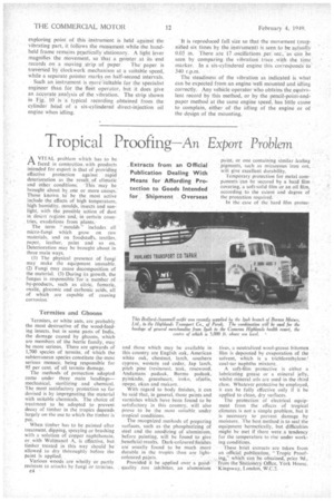
Such an instrument is inore'suitable for the specialist engineer than for the fleet operator, but it does give an accurate analysis of the vibration. The strip shown in Fig,. 10 is a typical recording obtained from the cylinder head of a six-cylindered direct-injection oil engine when idling.
"It is reproduced full size so that the movement (magnified six times by the instrument) is seen to be actually 0.05 in. There are 17 oscillations ,per. sec; as can be seen by comparing the vibration._ trace .With the time marker. In a six-cylindered engine this corresPonds to
340 r.p.m. '
The steadiness of the vibration as indicated is what can be expected from an engine well mounted and idling correctly. Any vehicle operator who obtains the.equivalent record by this method, or by the pencil-point-andpaper method at the same engine speed, has little cause to complain, either of the idling of the engine or of the design of the mounting.