


Developing Flexible-link Couplings
Page 55
If you've noticed an error in this article please click here to report it so we can fix it.
DUBING recent years the ShnmsJurid patent link couplings have made .consederable headway in the commercial-motor world. On the occasion of an interesting visit to the makers, Simms Motor Units, Ltd.,
Percy Buildings, Gresse Street, Rath. bole Place, London, W.1, we inspected a number of drawings of universal joints for some of the best-known makes of vehicle.
The basis of each link is a steel. wire loop made of stranded cable, after the fashion of a grummet. A length of cable is taken and a loop made at one end ; the free end is then passed through the loop and wound around it time after time until it forms an endless ring. This is done by hand.
The wire strands are cotton-covered and—this cotton is impregnated ; the individual strands are galvanized, thus rust is practically impossible. The minor axis of the loop is supported by a fabric buffer, whilst the loop passes around and rests upon steel bushes. The periphery of each bush is wrapped with Jurid—a very hard substance of the Bakelite type—which insulates the cable loops from the steel bush. To protect the parts from atmospheric influences the whole is encased in a rubber moulding To armour the ends of the link anti to ensure that the parts retain their correct relative positions under compression stresses, mild steel pressings are used.
These links are made in seven standard sizes, namely, 45 nm., 50 mm., 00 mm., 70 mm., 80 mm., 90 mm., and 100 ma. Special sizes can be made
to order. 'The safe loads which can be imposed upon these links range from 220 lb. to 2,116 lb., the breaking loads being approximately four times the safe loads. In the case of assembly into universal couplings the links are bolted into place under slight initial tension. They can be bolted up between two-. armed spiders to make a four-link coupling; a six-link design employs three-armed spiders, and so on. The links can also be fitted between flange mountings; this last type gives a smooth periphery and a comparatively small diameter.
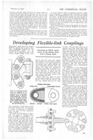
An application of the Simms-jurid link which is receiving increasing attention at the hands of designers, is as a flexible engine mounting. Briefly the system involves a Y-piece bolted between the frame flanges, carrying from the end of each arm a link which is bolted to the crankcase bearer. Aa the axes of the links are inclined to each other at an obtuse angle all engine torque reaction is countered. The forward mounting consists of a ball-type support.
Another direction in which the links can be made to serve the designer is as couplings between the ends of shockabsorber arms and frames or axles. It will be realized that, wore each axle to rise and fall in a plane at all times truly at right angles to the chassis frame, rigid couplings between the damper arms and the frame or axle would be possible. As the axle can rise or fall at only one end at a time, however, some provision must be made to permit the consequent twisting, and it is here that the Simms-Jurid link scores, for it can take tension, compression and torsional loads.