


Patents Completed.
Page 22
If you've noticed an error in this article please click here to report it so we can fix it.
Complete specifications of the following patents will be sent to any address in the United Kingdom upon receipt of eightpence per copy at Sales Branch, Patent Office, Holborn, W.C.
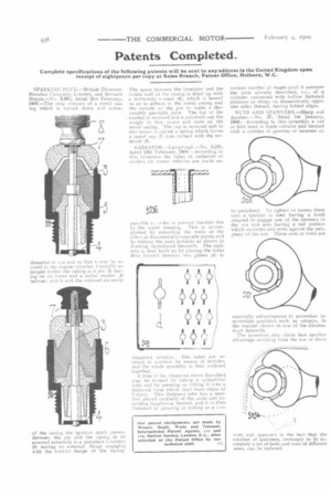
SPARKING PIXG.—British ThomsonHouston Company, Limited, and Bernard Hopps.—No. 3,983, dated 21st February, 1908.—The plug consists of a metal casing which is turned down and screw threaded at elle end so that it may be secured to the engine cylinder. Centrally arranged withifl the casing is a pin :3) having on its lower end a nickel washer between which and the screwed extremity
of the casing the i.gi ition spark passes. Between the pin and the casing at its screwed extremity is a porcelain insulator (5) having sit external flange engaging with the interior flange of the casing
The space betweee the insulator and the inside wall of the casing is filled up with a refractory enamel (6), which is heated so as to adhere to the metal casing and the outside of the pin to make a thoroughly gas-tight joint. The top of the enamel is recessed and a porcelain cap fits snugly in this recess and rests on the metal casing. The cap is recessed and in this recess is placed a spring which forces a metal cap t7) into contact with the terminal 8,1.
RADIATOR.—Lamplough.—No. 3,241, dated 13th February, 1908.--According to this invention the tubes of radiators or coolers on motor vehicles are made ex pansihle 1.1 order to prevent fracture due to the water freezing. This is accomplished by extending the walls of the tubes at diametrically-opposite points and by folding the ends inwards as shown in drawing reproduced herewith. The radiator is then built up by placing the tubes thus formed between two plates (d■ in staggered relation. The tubes are secured in position by means of ferrules, and the whole assembly is then soldered together.
A tube of the character above described may be formed by taking a cylindrical tube and by pressing or rolling it into a Battened form which shall have edges of V-form. This flattened tube has a mandrel placed centrally of the same and extending lengthwise thereof, and it is then flattened by pressing or rolling at a coil venient number of stages until it assumes the form already described, i.e., of a cylinder connected with hollow flattened portions or wings on diametrically opposite sides thereof, having folded edges.
NUTS AND SPANNERS.—Sharp and Another.—No. 37, dated 1st January, 1908.--According to this invention a nut or bolt head is made circular and formed with a number of grooves or recesses on
its periphery. To tighten or loosen these nuts a spanner is used having a knob adapted to engage one of the recesses in the nut and also having a tail portion which encircles and rests against the periphery of the nut. These nuts or bolts are
especially advantageous in somewhat inaccessible positions such as corners, in the manner shown in one of the illustrations herewith.
The inventors also claim that another advantage accruing from the use of these
nuts and spanners is the fact that the number of spanners, necessary to fit accurately a set of bolts and nuts of different sizes, can be reduced.