


Rotary Distributor: Injection Pump
Page 70
If you've noticed an error in this article please click here to report it so we can fix it.
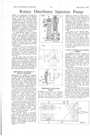
ONE, of the difficulties in designing a rotary distributor for an injection pump is that the spacing between adjacent outlets has to be small unless a distributor of inconveniently large diameter is employed. This means that the fit of the rotor in its sleeve must be practically .perfect if leakage is to be prevented. A design in which these difficulties are minimized is revealed in patent No. 698,258 by Robert Basch
G.m.b.H., Stuttgart-W., Germany.
A single-plunger pump is shown generally at 1. It feeds its output to a rotary distributing unit in the same casing. This consists of a Manger (2) which has a composite motion, partly rotary and partly reciprocating, as used
in some types of sleeve valve. The motion is derived from an angular crankpin (3) projecting from the main pump spindle.
A forked " big-end " (4) embraces the crankpin and works on trunnions carried by a member journalled on the crankpin. By this means, any point on the plunger is made to describe an elliptical path, thus spacing the outlets well apart As the upper space (5) above the distributing plunger plays no part in its action, it can be used as a separate pump for any desired duty, such as for pumping oil, or raising the fuel for the injection unit. For this purpose, it is fitted with an outlet .valve (6) and an inlet (7), the latter being controlled by the rising and falling of the plunger.
PREVENTING SCUFFING IN HEAVY TRAILERS
PATENT No. 698,063 (G. Kendall, 468 Grove Street, Windsor, Ontario, Canada), deals with improvements in heavy trailers. In the example shown the trailer has 12 wheels, divided into two sets of eight and four, the latter
being all steerable. The patent also covers the suspension system, which is based on the use of rubber sleeves.
The pairs of rear wheels are pivoted on rubber about an axisA-A, which permits, them to align themselves to road camber. Each group of four is carried on a beam, which is again pivoted on rubber, this time about a transverse axis B-B. The net effect is to give the wheels a universal movement in relation to road inequalities.
The most novel point is the manner in which all four front wheels move in unison when steering. Each pair is mounted on a king-pin (1) and carries an arm (2) pointing rearwards. The two arms are angled so as to comply with Ackerman geometry and are joined by a track-rod (3).
The drawbar, which is journalled about point 4, is pivoted to the trackrod at 5. When the drawbar is swung sideways, the wheels are steered to different angles, so that their axes all intersect approximately at the turning centre. Tyre scuffing is said to be practically eliminated. A40 THERMALLY ACTUATED CHOKE
rHOKES controlled by a bimetallic
strip responsive to the temperature of the engine are simple in principle, but in practice are found to fall short of requirements, in that it is
difficult to obtain an action that is faithful function of the engine temper ture. Progress in this respect is ti aim ofa scheme shown in patent N 698,224 by the Ford Motor Co., Lt( 88 Regent Street, London, W.I.
The bimetallic element is heated I a stream of air which has itself be heated by the exhaust gases. The hea exchanger used forms the subject of 0 patent.
The flow of the exhaust gases indicated by arrows. The gas imping op a helically rolled tube (1) which col tains an inner tube (2). This connected with the induction pipe ( the engine in such a manner that a enters the end (3) and after being heatc leaves through bore 4, whence it is fe to the bimetallic element that work the choke. The helical shell is mac of Inconel, stainless steel or other nor oxydizing alloy.
SAFETY CONTROL FOR TIPPING BODIES
ASCHEME shown in patent Isk 698,336 by W. W. Jenkins (Che
tenham), Ltd., Tclehoist • Work: Cheltenham, aims to prevent a hydrauli tipping body from overrunning its rara and getting out of control. A lim stop is provided in the form of a sma hydraulic ram which first resists th body movement and then acts as positive stop.
Referring to the drawing, 1 is a pal of main rams hydraulically powere, and controlled by a manual valvt Attached to the body is a lost-motio. quadrant (2) which, near the limit o tip, engages a small hydraulic ram (3; When the hydraulic power is appliee the small ram is first extended and thei the main rams come into operation. A the limit is approached, the small ran is forcibly compressed and finall: comes to a positive stop. This serve to decelerate the moving body beter. arresting its motion.
On the downstroke, the power is shu off from the main rams, but remain applied to the small one, so that thi descending body is given a useful pusl at the time when the gravitations moment is at its least effective point The maximum movement permittec by the control ram is about 75°.