


Scheme for Oil-cooling Valve Guides and Seats
Page 36
If you've noticed an error in this article please click here to report it so we can fix it.
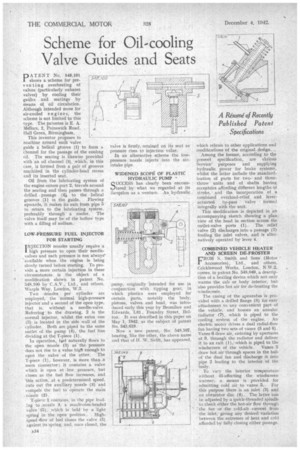
PA T EN T No, 548,101 shows a scheme for prey en t in g overheating of valves (particularly exhaust valves) by cooling their guides and seatings by means of oil circulation. Although intended more for air-cooled engine s, the scheme is not limited to this type. The patentee is E. A. Mellors, 2, Painswick Road, Hall Green, Birmingham.
This inventor proposes to machine around each valve guide a helical groove (1) to form a channel for the passage of the cooling oil. The seating is likewise provided with an oil channel (3), which, in this case, is formed from a pair of grooves machined in the cylinder-head recess and its inserted seat.
Oil from the lubricating system of the engine enters port 2, travels around the seating and then passes through a drilled passage (4)„ to the helical grooves (1) in the guide. Flowing wpwards, it makes its exit from pipe 5 lo return to the lubricating system, preferably through a cooler. The valve itself may be of the hollow type with a filling of sodium.
LOW-PRESSURE FUEL INJECTOR FOR STARTING INJECTION nozzles usually require a 1 high pressure to open their needlevalves and such pressure is not always' available when the engine is being slowly turned before starting. To provide a more certain injection in these circumstances is the object of a modification shown in patent No. 548,100 by C.A.V., Ltd., and Others, Warple Way, London, W.3.
Two ,nozzles per cylinder are employed, the normal high-pressUre injector and a second of the open type, that is, without a needle-valve. Referring to the drawing, 2 is the normal injector, whilst the extra one (3) is located in the side wall of the cylinder. Both are piped to the same outlet of the pump (4), the fuel line• dividing at the T-piece (1).
In operation, fuel naturally flows to the open nozzle (3) as the pressure does not rise to a value high enough to open the valve of the other. The T-piece (1), however, is More than a mere connector; it contains a valve which is open at low pressure, but closes as the fuel flow increases, and this action, at a predetermined speed, cuts out the auxiliary nozzle (3) and compels the fuel to op'erate the main nozzle (2).
T-pieee 1 contains, in the pipe leading to ,nozzle 3, a mushroOm-headed valve .(5), which is held by a light spring in the open position.. Highspeed -flow of fuel closes the valve (5) against its spring, and, once closed, the
valve is firmly, retained on its seat as pressure rises to injection value.
In an alternative scheme the lowpressure nozzle injects into the airintake pipe WIDENED SCOPfi OF PLASTIC HYDRAULIC PUMP
SUCCESS has clearly been encountered by what we regarded at its inception as a venture. An. hydraulic
pump, originally 'Intended for use in conjunction with tipping gear, in which plastics were employed for certain parts, notably the body. pistons, valves and head, was introduced early this year by Bromilow and Edwards, Ltd , Foundry Street, Bolton. It was described in this paper on May I, 1942, as the subject of patent No. 543,619.
Now a new patent, No. 548,107, bearing, like the other, the above name and that of II, W. Swift, has appeared. which ielates to other applications and modifications of the original design.
Among the former, according to the present specification, are Various Service' purposes and supplying hydraulic power for brake systems, whilst the latter include the standardization of parts for twoand three, throw units and of shafts having eccentrics affording different lengths of stroke, and the incorporation of a combined overload-relief and leveractuated by-pass valve formed integrally with the unit.
This modification is depicted in an accompanying sketch showing a plan: view of the head in section across the outlet-valve ports (1). The relief valve (2) discharges into a passage (3) feeding the inlet valves, and is alternatively operated by lever 4.
COMBINED VEHICLE HEATER AND SCREEN DE-FROSTER
FROM S. Smith and Sons" (Motor Accessories), Ltd., and others, Cricklewood Works, London, N.W.2, comes, in patent No. 548,049, a description of a heating device which not only warms the cab or body interior, but also provides hot air for de-frosting the windscreen, The casing of the apParatus is provided with a drilled flange (8) for easy attachment to any convenient part of the vehicle, and houses an annular. radiator (T), which is piped to the cooling system of the engine. An electric motor drives a dual radial-flow fan having two sets of vanes (5 and 6). Vanes 6 draw air, entering by apertures at 9, through the radiator and deliver it to an exit (I), which is piped to the
windscreen of the vehicle. Vanes 5 draw hot air through spaces.in the hub of the dual fan and 'discharge it into pipe 2 leading to the interior of the. body.
To vary the interior temperature without ill-affecting the windscreen • ,varrner, a means is provided for admitting cold air to vanes 5. For this purpose there is an inlet (3) and an obturator disc (4). . The latter can be adjusted by a quick-threaded spindle to check either the hot-air flow through the fan or the cold-air current from the inlet; giving any desired variation between the extremes of heat and cold afforded by fully closing either passage.