


A Steering Gearbox for Heavy Vehicles
Page 54
If you've noticed an error in this article please click here to report it so we can fix it.
FROM the Gemmer Manufacturing Company, Detroit, Michigan, U.S.A., comes patent No. 638,882, disclosing a design for a steering gear. Intended chiefly for the heavier types of vehicle, the gear is said to be proof against road-shocks reaching the steering wheel.
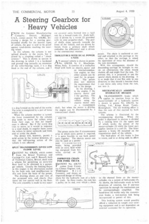
In this scheme, the column is not splined directly to the worm, but is joined by a coupling called a "shock arrester." This is shown in section in the drawing, in which 1 is a hardened and ground ring (actually an extension of the roller-bearing race), 2 is a dog fixed to the end of the column, and 3 is a dog formed on the end of the worm. The joint is completed by a pair of loose rollers (4).
When the column member is turned, the force transmitted by the column dog tends to move the rollers away from their cage, so that .hci impedance is offered. But if the worm dog tries io move, as it would in response to a road shock, its angular faces cause the rollers to .move outwards and bihd, and so' arrest the shock.
The device wilt, however, permit a mild action in the reverse 'direction, so that the -selfzsteering action of the vehicle is not affected.
SPLIT*TRANSMISSION GIVES LOW • FLOOR LEVEL DATENT N. 638,426, , which comes
from the Bristol Tramways and Carriage Co., Ltd., and F. Boswell, both of Tramways Centre, Bristol, deals with a scheme for permitting an extra-low floor level to be obtained in a passenger vehicle. Usually the limiting factor in this respect is the obstruction cau;ed by the back axle, and modifications to this unit form the basis of the patent.
The drawing shows .an end view, of the proposed axle, and clearly illustrates the low central well in the floor. The axle assembly is made -in two separ
ate co-axial units formed into a rigid unit by a bowed trunk (1). Each halfaxle is driven by a worm (2) provided with its own propeller-shaft. The pair of shafts slope upwards towards the front of the vehicle, and are driven by bevels from a primary shaft which embodies the differential and is driven in the conventional manner.
TROLLEYBUS WITH DUAL POWER UNITS
AN unusual vehicle is shown in patent No. 638,918, by C. Mascherpa, Milan, Italy. It consists of a trolleybus fitted with both an electric. motor and an internal-combustion engine, so that either system can be used for its propulsion. The patent does not mention the requirement that led to the design.
In the drawing, 1 is the engine, 2 the electric motor and 3 the gearbox. The engine drives the vehicle using the electric motor only as a transmission shaft, but when the motor is driving, the engine can be disconnected by a conventional clutch.
The patent stales that if circumstances arise in which extra power is required. it is quite feasible to use both power units together. The electric motor can also be used as a perma
nent transmission brake, being provided' with an extra field winding energized from batteries carried on the vehicle.
IMPROVED CHAIN FOR FORK TRUCK PATENT No. 638,735 comes from Coventry Climax Engines, Ltd.,
Widdrington R o a d. Coventry, and shows an improved design of lifting chain for the hydraulic ram of a forklift truck. In these trucks, the .ram has. a pulley on its end, over which a chain passes. The chain is anchored at one end and attached to the carriage at the other, so that. the carriage is raised the equivalent of twice the distance of the ram movement.
With this arrangement, should the descending carriage be brought to rest on an obstruction, the chain would slacken off and might foul the ram. To prevent this, it is proposed to use the special chain shown in the drawing. It is so made that it can-flex only in one direction, so that should it become slack it can move only away from the ram, not into it.
MECHANICALLY ASSISTED HYDRAULIC BRAKES
ATRANSMISSION brake which applies its reaction force to the master-cylinder of a hydraulic system is shown in patent No. 638,332, by Girling, Ltd., Kings Road, Tysely, Birmingham. The net braking effort is thus the sum of that exerted by both systems.
The scheme is illustrated by the accompanying drawing. When the pedal is depressed its motion is divided by a rocking lever (1) the upper end of which works the piston of the master-cylinder (2) while the lower part applies tension to a 'rod (3), The latter operates a brake (4) mounted on the transmission shaft of the vehicle.
The back-plate of this brake is free to rotate, and in so doing adds its effort to ' the manual force on the mastercylinder, via a system of bell-cranks (5). As shown, the bell-cranks work in both directions of rotation, but if one-way operation be enough the mechanism can be correspondingly. simplified. The hand-lever (6) works only the transmission brake, .a lost-motion link being incorporated to permit of this.
This braking system would possibly afford a reduction in weight over existing equipment and is not dependent on external assistance for its operation.