A Free Wheel and
Page 56

If you've noticed an error in this article please click here to report it so we can fix it.
Centrifugal Clutch
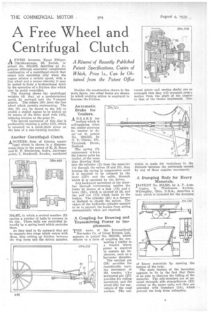
A SWISS inventor; Ernst Pfliiger, Claridenstrasse, 36, Zurich, in patent No. 394,508, describes an ingenious although somewhat complicated combination of a centrifugal clutch that comes into operation only when the engine attains a certain speed, with a free wheel and a means whereby it may be locked to form a hi-directional drive by the operation of a friction disc which may be pedal controlled.
The drawing shows the centrifugal weights (4) that, at a predetermined speed, fly outward into the V-shaped groove. The rollers (8") form the free wheel which permits overrunning. The disc (9) can be forced to the left to enable a stalled engine to be picked up by means of the three push rods (10), inducing friction at the point 9A.
'The lateral movement of this disc is produced by rotating a collar (12), which is mounted on a quick-pitch screw on the boss of a non-rotating member.
Another Centrifugal Clutch.
ANOTHER form of friction centri fugal clutch is shown in a diagrammatic form in the patent of K. E. Steen and [E. F. Sundstrom, Sodra, Jarnvagsgatan, 7, Sundsvall, Sweden, numbered 394,467, in which a central member (9) carries a number of balls in recesses in its rim. These balls are controlled inwardly by a spring band which encircles them.
As they tend to fly outward they act to separate two rings which rotate with them, thus setting up friction between the ring faces and the driven member. Besides the construction shown in the main figure, two other forms are shown in which wedging action is employed to increase the friction.
Automatic Brake for Trailers.
ABRAKE for trailers which is self-applying when the trailer overruns its tractor is (loser' ;ed in patent No. 394,323, by C. V. Clarke, 171, Tavistoelt Street, Bedford.
The spring (7) compresses when the tractor pulls its trailer, at the same time drawing fluid into the cylinder (3) from the reservoir (8) through the valves (9 and 10), thus keeping the spring in compression until it is required to be released by the lever (121) and the cable, through which it is operated by the driver.
Any backward movement of the drawbar through overrunning applies the brake by means of a link (14) and a lever (15), which is pivoted at 16, and the pull rod (17) which leads to the brakes. The cylinder (21) is a damper or dashpot to steady the action. The object of the hydraulic cylinder appears to be to prevent the brakes from acting automatically when not required.
A Coupling for Drawing and Transmitting Power to Implements.
THE name of the International Harvester Co. of Great Britain, Ltd., appears in patent No. 394,535, which relates to a form of coupling for con necting a trailer to a tractor where power is required to operate an implement, such as a harvester thresher.
The vertical pin (24) provides for considerable turning movement of the tractor, t h e horizontal pin (27) provides for rolling movement, and the pivot (33) for curvature•of the road surface. The uni
versal joints and cardan, shafts are so arranged that they will transmit rotary motion from the shaft of the tractor to that of the trailer implement. Pro vision is made for variations in the distance between the universals caused by any of these angular. movements.
A Dumping Body for Heavy Materials.
PATENT No. 394,598, by A. P. Armington, 8, Waldemere Avenue, Willoughby, Ohio, U.S.A., describes a body which is intended for the dumping of heavy materials by opening the bottom of the body.
The main feature of the invention appears to lie in the fact that there is no axle to obstruct the falling of the material. The side-members are of unusual strength, side strengtthners (12) extend to the upper rails, and they are Provided with crossbars (14), which prevent the body from collapsing.


