


LEAN LINES FO FII GI I
Page 40
Page 41
If you've noticed an error in this article please click here to report it so we can fix it.
FO
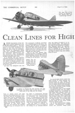
MAN CE A. BRIEF description of the Airspeed Courier appeared in our issue dated April 7. The first Courier to be produced had not then flown so that only calculated performance data could be published. The results of subsequent flying tests have exceeded expectations, the retractable undercarriage and the extremely clean aerodynamic form having more than justified the trouble expended upon them.
It is because this new machine embodies features of design that are only commencing to be adopted, but are likely to become general, that we now provide readers with a full description obtained by examination of the aircraft.
In short the designer's aim has been to obtain speed and high general performance more by reducing drag than by increasing horsepower (and, with it, operating cost). With its single engine, retractable undercarriage and rounded, streamlined contours it resembles to some extent the German Heinkel He 70 (described in this paper dated May 12), but whereas the Heinkel nses 630 b.h.p. to transport four •or 1330 five passengers (1,100 lb. pay-load) at a cruising speed of 203 m.p.h., the Courier uses 240 b.h.p. to transport five passengers (824 lb. pay-load) at 143 m.p.h. The lower power per passenger (48 b.h.p.) and per cwt. payload (32.7 b.h.p.) are attractive considering the high speed.
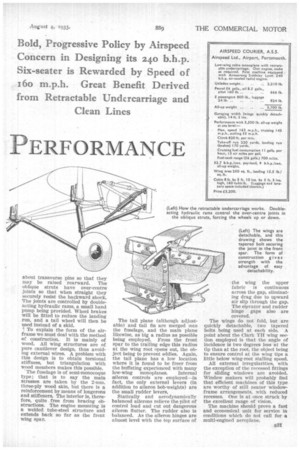
This is the first British commercial machine to employ a folding undercarriage, and the difference in speed with this folded or extended is found to be 35 m.p.h. The brak ing effect is emphasized because naturally no attempt has been made to streamline the undercarriage struts. A ready-made air brake thus presents itself, facilitating the landing of a machine which, through cleanness of form, would otherwise have an inconveniently long glide.
The top speed is reduced by approximately 4 m.p.h. by reason of the fitting of an exhaust-collector
ring, the object of which is to reduce exhaust noise. The gases are led away in two streams to Burgesstype silencers below the fuselage, further limiting the noise. The engine is enclosed by a clean-fitting cowling and around this is a Townend ring to reduce drag, this adding about 15 m.p.h.
An electric-light device shows the pilot exactly in what position the undercarriage is and should he throttle down his engine an electric horn or similar device will warn him to lower the wheels before landing. This takes 2i seconds, whilst raising them takes nine seconds.
An important point is that should a landing be made with the undercarriage folded the probability is that little more damage would result than a broken propeller and, perhaps, strained engine mountings. The reason is that when raised the wheels still protrude a little from the wing cavities. It is thought that a forced landing in very marshy ground might be the better made with the wheels raised.
As to the undercarriage design, Vickers oleo-pneumatic vertical struts are provided which pivot
about transverse pins so that they may be raised rearward. The oblique struts have over-centre joints so that when straight they securely resist the back-ward shock. The joints are controlled by doubleacting hydraulic rams, a small hand pump being provided. Wheel brakes will be fitted to reduce the landing run, and a tail wheel will then be used instead of a skid.
4 To explain the form of the airframe we must deal with the method of construction. It is mainly of wood. All wing structures are of pure cantilever design, thus avoiding external wires. A problem with this design is to obtain torsional stiffness, but triangulation with wood members makes this possible. 'The fuselage is of semi-monocoque type; that is to say the main stresses are taken by the 2-mm. three-ply wood skin, but there is a reinforcement by means of longerons and stiffeners. The interior is, therefore, quite free from bracing obstructions. The engine mounting is a welded tube-steel structure and extends back so far as the front wing spar.
The tail plane (although adjustable) and tail fin are merged into the fuselage, and the main plane likewise, as big a radius as possible being employed. From the front spar to the trailing edge this radius at the wing root opens out, the object being to prevent eddies. Again, the tail plane has a low location where it is found to be freer from the buffeting experienced with many low-wing monoplanes. Internal aileron controls are employed—in fact, the only external levers (in addition to aileron bob-weights) are the small rudder levers.
Statically and aerodynamically balanced ailerons relieve the pilot of control load and cut out dangerous aileron flutter. The rudder also is balanced. As the aileron hinges are almost level with the top surface of the wing the upper fabric is continuous across the gap, eliminating drag due to upward air slip through the gap. The elevator and rudder hinge gaps also are covered.
The wings do not fold, but are quickly detachable, two tapered bolts being used at each side. A point about the Clark YH wing section employed is that the angle of incidence is two degrees less at the tip than at the root, the object being to ensure control at the wing tips a little below wing-root stalling speed.
All external irregularities, with the exception of the recessed fittings for sliding windows are avoided. Window makers will probably find that efficient machines of this type are worthy of still neater windowframe arrangements, with reduced recesses. One is at once struck by the excellent range of vision.
The machine should prove a fast and economical unit for service in conditions which do not call for a multi-engined aeroplane.