


AN AUTOMATIC HYDRAULIC CLUTCH.
Page 28
If you've noticed an error in this article please click here to report it so we can fix it.
A Résumé of Recently Published Patent Specifications.
THO well-known name of Louis Renault appears again, this time in connection with an automatic hydraulic clutch, in patent No. 212,519. The invention relates to a clutch which is particularly adapted 'for use on vehicles
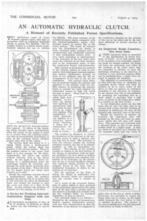
which are operated by internal-combustion engines. It allows of the clutching being brought about automatically when the torque of the engine is equal to, or greater than, the resisting torque, and also of automatically declutching so soon as the resisting torque becomes greater than that of the engine. -
The driving shaft has keyed to it a casing which forms a double-geared pump, whilst the driven shaft has keyed to it the central pinion. When in the position shown in the upper view there is a free passage for the fluid ; consequently, the driver can revolve without carrying with it the driven shaft. As the speed of the driver increases to a predetermined, point the centrifugal weights fly outwards, and, through the racks shown, gradually close the passage of the fluid. When the fluid can no longer travel ,the whole mass revolves as a solid.
Should the resistance increase beyond a predetermined point the pressure against the pistons will be so great that it will overcome the effect of centrifugal force, and compel the pistons to open the ports and allow of a flow of the fluid. Arrows indicate the direction of rotation and the passage of the fluid.
A Device for Working Internalcombustion Engines with any Fuel.
AN interesting specification is that of H. F. Steffens, of Holland, in which be points out the following in patent
B44 .
No. 207,811. The great economy of the constant-pressure engine compared with the internal-combustion engine (carburetter motor) is mainly due to the better mixing. The motor oil injected into the incandescent air charge is finely atomized under pressure and instantaneously and completely vaporized so that condensation cannot occur. A very rapid ,activating or disintegration of the molecules of the fuel takes place under the influence of the high temperature in the compression space, so that the combustion begins instantaneously.
This method of producing the mixture in the cylinder cannot be used in connection with high-speed internal-combustion engines (carburetter motors) as there is not sufficient time for the rearrangement of the fuel in the air for combustion. The mixture must therefore be prepared outside the cylinder and admitted to the cylinder ready for use. This manner of producing the mixture limits in general the fuels adapted for carburetter motors to light oils which are easy to spray. These fuels do, however, as a rule, not allow high com
pression p r e ssure, as premature ignitions by spontaneous ignition must be prevented in explosion engines. The temperature at which spontaneous ignition of a charge occurs forms, therefore, a sharp line of demarcation between the t w o kinds of engine.
The problem is, therefore, to control the formation of the mixture in the carlinretter motor in such a manner that any fuel may be used. The necessity to form the mixture outside the working cylinders remains, but has to be slightly modified, as will be hereinafter explained. The solution of the problem consists in adding to the fuel mixture of the charge, in accordance with its igniting capability, the heat which is lacking for the disintegration and complete combustion of its molecules, by the detonation of one or several auxiliary charges. The explosion shocks produce by their pressure waves at the same time a mechanical formation of eddies in the mixture of air and fuel.
For the spraying of the flows of charge the charge is subdivided into several currents which are introduced into the cylinder from a number of points.
As a result of the increased formation of eddies which is thus produced in the combustion space and at the same time of the fact that a greater part of the mixture is 'brought into contact with the hot cylinder walls, an increased absorption of heat is ensured.
The principal claim is as follows :Method for the working of j.nternal-combustionengines (carburetter motors) with any fuel, characterized in that the formation of the mixture is completed in the combustion chamber by the striking of the one on the other and by the intimate admixing of several currents of charge.
An Improved Brake Construction from Italy.
A VERY ingenious brake is described
in the specification of Guido Fornaca, of Turin. It is well known that if two members of an internally expanding brake are hinged together, the hinge not being the anchorage, and either of the members at the point where they are expanded is allowed to form the anchorage according to the direction of rotation, a very powerful braking effect can be produced from a slight force exerted to expand the members.
The difficulty in constructing a brake of this kind has been in designing an expanding device which will alter its position so as to allow either of the shoes to take up against an abutment according to the direction of rotation. In the present case this is accomplished by mounting the expanding cam on a shaft which is provided with a ball joint, as shown in the lower view, which is a section on the line (C-D).
In the illustration given on the left hand will he seen the shoe that is in contact with a boss, thereby forming an abutment or anchorage, the shoe on the opposite side standing clear of the boss.
Should the direction of rotation he reversed, the right-hand shoe will impinge on the boss and form an abutment, whilst the left shoe will stand clear. The expander cam is formed with a spherical head, so that it can accommodate itself at a slight angle. A sliding block is provided as a bearing for the expander shaft, and can move to either aide of the slot in which it slides. Set-screws are provided to centre the brake when not in action, as the hinge which connects the two halves is free to oscillate as shown. The number of the patent specification for this improved construction of brake is 232,115.