


Tyre Using Silicones and Glass H EAVY loads and high speeds
Page 76
If you've noticed an error in this article please click here to report it so we can fix it.
are 'placing an ever increasing burden on conventional rubber and cord tyres, Especially is this so in tyres used on heavy lorries; these have a tendency to de-laminate because of the heat generated by the hysteresis, of the rubber. Such are the views expressed in patent No. 790,676 which describes a tyre built of silicone rubber and glass cords. (Midland Silicones, Ltd., 19 Upper Brook Street, London, W.I.) One of the chief problems is said to be the brittleneSs-of the glasS Cords and the patent deals with a ,way of overcoming it. The individual glass filaments, having a diameter of only 0.0002., in are first coated' 'Withone of Chic substances known as silOxaricS: They are died
. .
gathered into strands of 200 andheated to 'Cure the silbxanc: •
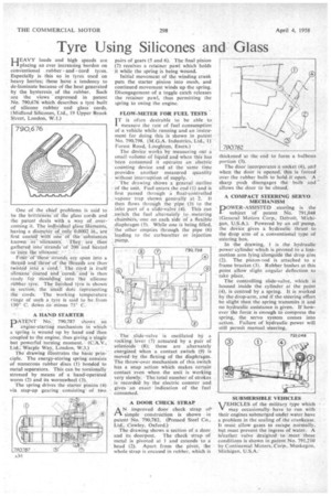
Four Of these Strands arc spun into a threadand ilitee of the 'threads are then twisted into a 'cord .= The cord is itself silbxMie `cOated and 'cured: and is then ready for Moulding into the silicone rubber tYre. The finished Ore is shown in ,section; the small dot S representing the cords. The Working temperature ra:pge of such a tyre is said to be from 150° C. doWn .n1.1/firms 75° C.
A HAND STARTER
DATE. NT 790,787 shows an
I engine-starting mechanism Which
a Spring is wound up by hand and then coupled to the engine, thus giving a single but powerful turning moment. (C.A.V.,
Ltd Warple Way, London, W.3.) •
The drawing illustrates the basic priri-ciple. The energy-storing spring consists of numerous rubber discs (1) bonded to metal separators. This can be torsionally stressed by means of a hand-operated worm (2) and its wormwheel (3).
The spring drives the starter pinion (4) via step-up gearing consisting of two pairs of gears (5 and 6). The final pinion (7) receives a retainer pawl which holds it while the spring is being wound.
Initial movement of the winding crank puts the starter pinion into mesh, and continued movement winds up the spring. Disengagement-of a toggle catch releases the retainer pawl, thus permitting the spring to swing the engine.
FLOW-METER FOR FUEL TESTS
I T is often desirable to be able to measure the rate of fuel consumption of -a vehicle while running and an instrument, for doing this is shown in patent No. 790,798. (M,G.A. Industries, Ltd.,-11 Forest Road, Loughton, Essex.)
The device works by measuring out asmall volume of liquid'and when this has been consumed it operates an electric coUnting device and at the 'same time provides another measured quantity
without interruption of supply. • • ..• The drawing shows a' general .outline of the unit. Fuel enters the end (.1) and is first passed through a Moat:controlled • , vapour trap shown generally "at-2.It then flows thrcingit the pipe_ (3) to the inlet port of a slide-valve (4). This can .switch the fuel alternately ;ometering
metering chambers, one on each .side of a -flexible diaphragm (5). While one is being filled, the other empties through the pipe (6) leading to the carburetter or injection pump, The slide-valve is oscillated bY rocking, lever (7) actuated by a pair of solenoids (8); these are alternately energized when a contact switch (9) is moved by the flexing of the diaphragm. The throw-over mechanism of this Switch has a snap action which makes certain contact even when the unit is working very slowly. The total number of strokes is recorded by the electric counter and gives an exact indication of the fuel con surned.
A DOOR CHECK STRAP A N improved door check strap ob' rl simple construction is shown in patent No. 790,782. (Pressed Steel Co., Ltd., CoWley, Oxford.) The drawing shows a section of a door and its doorpost. The check strap of metal is pivoted at 1 and extends to a head (2). Apart from the pivot, the whole strap is encased in rubber, which is thickened at the end portion (3).
The door incorporates a scicket (4), and When the door is opened, this is forced over the rubber bulb to hold it open. A sharp push disengages the bulb and allows the door to be closed.
A COMPACT STEERING SERVO . MECHANISM
ROWER-ASSISTED , steering is the L subject of patent No. 791,048 (General Motors Corp., Detroit, Michigan, U.S.A.). Powered by an oil pump, the device gives a hydraulic thrust to the drop arm of a conventional type of steering box.
In the drawing, 1 is the hydraulic power cylinder which is pivoted to a lostmotion arm lying alongside the drop arm (2). The piston-rod is attached to a frame bracket (3). Rubber bushes at this point allow slight angular deflection to take place.
The controlling slide-valve, which is housed inside the cylinder at the point (4), is centred by a spring. It is worked by the drop-arm, and if the steering effort be slight then the spring transmits it and no hydraulic assistance is given. If however the force is enough to compress the spring, the servo system comes into action. Failure of hydraulic power will still permit manual steering.
SUBMERSIBLE VEHICLES
VEHICLES of the military type which v may occasionally have to run with their engines submerged under water have a problem in the sealing of the crankcase. It must allow gases to escape normally, but must prevent the ingress of water. A breather valve designed to meet these conditions is shown in patent No. 791,210 by Continental Motors, Corp.. Muskegon, Michigan, U.S.A.