


Integral PoN8 ,
Page 42
Page 43
If you've noticed an error in this article please click here to report it so we can fix it.
)rive Unit in New Vehicle
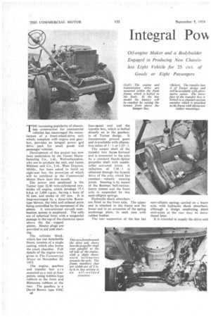
Oil-engine Maker and a Bodybuilder Engaged in Producing New Chassisless Light Vehicle for 25 cwt. of Goods or Eight Passengers
THE increasing popularity of chassisless construction for commercial vehicles has encouraged the manufacture of a front-wheel-drive unit which, complete with engine and gearbox, provides an integral 'power vid drive pack for small goods and passenger ' vehicles.
Development of this project has now been undertaken by the Turner Manufacturing Co., Ltd„ Wolverhampton, who are to produce the unit, and James Whitson and Co., Ltd., West Drayton, Middx., has been asked to build an eight-seat bus, the prototype of which will be exhibited at the Commercial Motor Show later this month.
The power unit employed is the Turner type 21.90 twin-eylindered twostroke oil engine, which develops 37.5 b.h.p, at 2,800 r.p.,m„ having a bore of 92 mm. and stroke of 105 mm. It is loop-scavenged by. a three-lobe Rootstype blower, the inlet and exhaust ports being controlled by the movement of the piston. A conventional air-cell combustion system is employed. The cells are of spherical form with a tangential passage to the top of the clearance space above the flat topped piston. Heater plugs are provided to aid cold starting.
The cylinder block, which has Wet detachable liners, consists of a single casting, which also forms the crank chamber. Full details of the engine were given in The Commercial Motor on November 20, 1953.
The engine, gearbox and transfer box a r e mounted as a unit at four points, using bobbin-type rubbers at the front and IvIetacone rubbers at the rear. The gearbox is a David Brown type 430C 138 four-speed unit and the transfer box, which is bolted directly on to the gearbox, is of Turner design. It incorporates ground gears and is available with alternative ratios of 1: 1 or 1.25 : 1.
The output shaft of the transfer box faces forward and is connected to the axle by a standard Hardy-Spicer propeller shaft with needleroller universal joints. A reduction of 3.98 : I is obtained through the hypoid drive of the axle, which has constant velocity steering joints. Steering is by means of the Burman ball-recirculatory system and the front axle is suspended by two semi-elliptic springs.
Hydraulic shock absorbers are fitted to the front axle. The upper end is attached to the frame and the lower end to an extension of the spring anchorage plate, in each case with rubber bushes.
The rear suspension of the bus has semi-elliptic springs carried on a beam axle, with hydraulic shock absorbers, although a design employing short stub-axles at the rear may be introduced later: It is intended to supply the drive unit complete with front wheels, having 6-in. by 16-in. tyres. Two-leading-shoe brakes are hydraulically operated; and to utable bodybuilders easily to connect the rear brakes to the braking system of the front drive assembly, a quickaction coupling is provided at the rear cross-member of the unit. The Borg and Beck clutch is also hydraulically operated.
Brake and wheel equipment for the rear section will not be supplied by Turners, although the type to be used will be the same as at the front.
12-volt Electrical Equipment
Electrical equipment operates on 12 volts, a 130-amp.-hour battery being supplied. All wiring is contained in the front drive unit, except that for the tail and stop lights, for which a quickaction plug is provided.
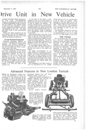
The short frame on which the power and drive components of the Turner front unit are mounted consists of two longitudinal members of steel box section, 3 in. by 6 in. at the rear and tapering to 3 in. by 3 in., where they form the wheel-arches. The rear crossmember, which is also of 3-in. by 6-in. box section, is welded to the Tear ends of the longitudinal members, which extend 4 in. from the back of the transfer box. At the front of the frame a crossmember of 3-in. by 3-in box section is placed just forward of the axle line and is used to support the radiator. An inverted channel-section cross-member is welded to the front ends of the longitudinal members, the space between the two front cross-members being used to house the battery, which is supported in a pressed-steel cradle, spot-welded to the frame.
Pads are provided at the sides of the frame to take the main body members, which, in the case of the eight-seat bus, will be of pressed-steel channel section, reinforced where necessary. The body, which is of light-alloy construction, is designed to form the basis of a small bus or a 25-cwt. van or pick-up.
A rear-hinged bonnet opens from a point" just above the front bumper to provide easy access to the engine and battery.
By slight re-arrangement of the engine position it is possible to accommodate the Turner three-cylindered oil engine and it is later intended to build a 16-seat bus of similar design for use with this type of front-drive unit. Other applications of the smaller version that are envisaged are school buses and ambulances.
The wheelbase of the Show model is 9 ft. 6 in. and track 4 ft. 2 in. Height of the body is 6 ft_ 3 in., and the floor is 20 in. above the ground. These dimensions will also apply to the van and pick-up versions that will be available. These will have cabs measuring 4 ft. 6 in, from floor to roof, 3 ft. 4 in, from bulkhead to back of cab, and 5 ft, 3 in. wide.
The dimensions behind the cab give a van capacity of 150 cu, ft., with an internal height of 4 ft. 6 in., width of 5 ft. 3 in. and length of 6 ft. 9 in.
Little Vibration
For test purposes the unit was fitted to a " mock-up" tubular chassis with temporary seats and engine covers. In this form it was noticed that engine vibration was almost completely isolated by the resilient mounting, and the noise was reasonable. The engine responded in lively -fashion to the plunger-type accelerator pedal, which is connected to the governor by cable.
This development marks an important step in the simplification of vehicle design. It provides the bodybuilder with a complete power and transmission unit to fit into a chassisless body structure, or enables a chassis to be designed to suit the body. Light weight is made possible without sacrificing the strength and rigidity of the engine mounting or the transmission system.