


New Principle in Suspension Systems
Page 54
If you've noticed an error in this article please click here to report it so we can fix it.
A Resurnj of Recently Published Patent Specifications
DAUNT No. 601,731 comes from I S. A. Andre Citroen, of Paris, and deals with a means for interconnecting the front and rear springing of a vehicle, the object being to give better riding qualities.
The drawing is diagrammatic and illustrates the basic principle of the scheme. Each wheel is mounted on a bell-crank (1), the shorter end of which is provided with two spring-anchorage points (2). Springs (3) connect the front and rear bell-cranks, the important feature being that the upper spring at the front becomes the lower one at the rear, and vice versa, so that the springs cross over mid-way. Each side of the vehicle is similarly arranged, but it is a feature of the patent that the two sides are not connected in any way. The patent also illustrates the same system employing hydraulicpneumatic suspension instead of springs.
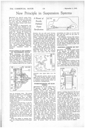
INNOVATIONS IN NEW HYDRAULIC TRANSMISSION SYSTEM rrliE advantages and defects of I torque-converters are compared in patent No. 602,020, which comes from the Ford Motor Co., Ltd,, 88, Regent Street, London, W.I. The statement is made that whereas a torque-converter will provide an efficiency of 85 per cent. at a redaction ratio of 2i to I, this is near its maximum value. The patent proceeds to describe a combination of torque-converter with a straightthrough mechanical drive, this being automatically established whenever the engine speed rises to a pre-determined number of r.p.m.
Referring to the drawing, I is the flywheel-driven impeller, 2 the driven or output member, and 3 a reaction rotor controlled by a one-way clutch. So much is standard practice in torqueconverter, design. The novel point is the provision of a plate-clutch (4), carried on the output member and running close to the flywheel. Oil is present between the friction-facing and the flywheel, and no drive occurs when at rest.
When the engine is running, however, oil is flung outwards to the largest diameter, but can still reach between the plates because of the presence of small ports drilled through the friction facings. When the engine speed rises to a predetermined value, centrifugally operated valve (5) close, cutting off the supply of oil, whilst external valves (6) are opened and create an escape path for the oil already between the plates.
The effect is to allow the plates to come together, gently but forcibly, owing to the high centrifugal pressure prevailing—about 40 lb. per sq. in. When the speed falls, the converse action takes place, and the torque converter once again takes over the drive.
The epicyclic gearbox, shown on the right of the drawing, provides a choice of forward or reverse drive, and gives a positively locked position which can be used for a parking brake.
FINISH-MACHINING OF GEARWHEELS PATENT No. 601,758, conies front a specialist in gear cutting, The Fellows Gear Shaper Co., Windsor, Vermont, U.S.A., and shows the latest scheme for giving a good finish to the form of gear-teeth. The known process of gear-shaving will give a good and accurate finish, but it is a slow operation and the cutters are expensive to make. The present scheme is said to give comparable results in much less time and using standard instead of special cutters.
Referring to the drawing, the gear (1) to be treated is located in the path of a cutter (2) of the correct form, as in standard gear-cutting, but in this case the gear has already been machined almost to finished size. The cutter is then slowly fed into the gear-teeth while they both quickly revolve in mesh. The result is a helical path of cut which is said to distribute the unavoidably, small inaccuracies of the machine uniformly between all the teeth. If several "bites" are taken,
precautions are taken to see that the gear and the cutter do not meet at the same teeth.
The difference between this scheme and the ordinary gear-shaping operation should be clearly grasped; in the latter the cutter reciprocates quickly and the pair revolve slowly, but in the present scheme fotation is rapid .and reciprocation slow.
INGENIOUS COOLING OF WET LINERS
PATENT No. 601,894 comes from H. Ricardo, 21, Suffolk Street, London, S.W.I, and discloses a new method of cooling cylinder liners. The chief aim is to enable the several cylinders of a multi-cylindered engine to be closely spaced and yet to provide adequate cooling.
The drawing shows a section of one of the cylinders of a four-stroke oil engine. The liner (1) is held in place by a registering ring (2) having studs (not shown) which force the liner firmly against a packing ring (3) at the top of the cylinder. Concentricity and water sealing are preserved by the use of a pair of rubber rings (4) located in grooves turned in the liner, The chief feature is the use of a helical coil of square wire (5) which surrounds the liner and compels the water to make several circuits as it passes through. The water is pumped at high velocity and enters through a common gantry (6) and, after traversing the helix, passes through pipe 7 and is directed by a second pipe (8) towards a point, in the head between the two valves. It then leaves the cylinder head by the normal return pipe.
A noteworthy feature is that the liner is not subjected to cylinder pressure in a vertical direction, and it can therefore be quite lightly held in place On that account it is the easier to replace.